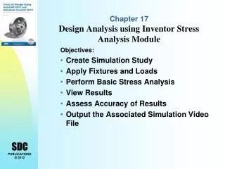
Chapter 17 Design Analysis using Inventor Stress Analysis Module
Chapter 17 Design Analysis using Inventor Stress Analysis Module. Objectives: Create Simulation Study Apply Fixtures and Loads Perform Basic Stress Analysis View Results Assess Accuracy of Results Output the Associated Simulation Video File. Design analysis.

Chapter 17 Design Analysis using Inventor Stress Analysis Module
E N D
Presentation Transcript
Chapter 17 Design Analysis using Inventor Stress Analysis Module Objectives: • Create Simulation Study • Apply Fixtures and Loads • Perform Basic Stress Analysis • View Results • Assess Accuracy of Results • Output the Associated Simulation Video File
Design analysis In this chapter we will explore basic design analysis using Inventor Stress Analysis Module. The stress analysis module is a special module available for part, sheet metal, and assembly documents. The Stress Analysis Module has commands unique to its purpose. With Autodesk Inventor 2013, Contact Analysis,Frame Analysis and Dynamic Analysis can also be performed. Inventor Stress Analysis Module provides a tool for basic stress analysis, allowing the user to examine the effects of applied forces on a design. Displacements, strains, and stresses in a part are calculated based on material properties, fixtures, and applied loads. Stress results can be compared to material properties, such as yield strength, to perform failure analysis. The results can also be used to identify critical areas, calculate safety factors at various regions, and simulate deformation. Inventor Stress Analysis Module provides an easy-to-use method within the Autodesk Inventor’s Stress Analysis Module to perform an initial stress analysis. The results can be used to improve the design.
STRESS Linear Elastic region Yield Point STRAIN Elastic Plastic Linear static analysis In Inventor Stress Analysis Module, stresses are calculated using linear static analysis based on the finite element method. Linear static analysis is appropriate if deflections are small and vary only slowly. Linear static analysis omits time as a variable. It also excludes plastic action and deflections that change the way loads are applied. The finite element method (FEM) is a numerical method for finding approximate solutions to complex systems. The technique is widely used for the solution of complex problems in engineering mechanics. Analysis using the method is called finite element analysis (FEA)
Finite Element Analysis In the finite element method, a complex system is modeled as an equivalent system of smaller bodies of simple shape, or elements, which are interconnected at common points called nodes. This process is called discretization, an example is shown in the figures below. The mathematic equations for the system are formulated first for each finite element; and the resulting system of equations is solved simultaneously to obtain an approximate solution for the entire system. In general, a better approximation is obtained by increasing the number of elements, which will require more computing time and resources.
Problem Statement Determine the maximum normal stress that loading produces in the aluminum plate.
Preliminary Analysis The nominal normal stress developed at the smallest cross section (through the center of the hole) in the plate is Geometric factor = .75/2 = 0.375 Stress concentration factor K is obtained from the graph, K = 2.27
Finite Element Analysis Procedure 1. Preliminary Analysis. 2. Preparation of the finite element model: a. Model the problem into finite elements. b. Prescribe the geometric and material information of the system. c. Prescribe how the system is supported. d. Prescribe how the loads are applied to the system. 3.Perform calculations: a. Generate a stiffness matrix of each element b. Assemble the individual stiffness matrices to obtain the overall, or global, stiffness matrix. c. Solve the global equations and compute displacements, strains, and stresses. 4. Post-processing of the results: a. Viewing the stress contours and the displaced shape. b. checking any discrepancy between the preliminary analysis results and the FEA results.