MOCVD
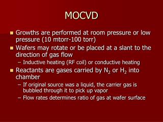
MOCVD. Growths are performed at room pressure or low pressure (10 mtorr-100 torr) Wafers may rotate or be placed at a slant to the direction of gas flow Inductive heating (RF coil) or conductive heating Reactants are gases carried by N 2 or H 2 into chamber

MOCVD
E N D
Presentation Transcript
MOCVD • Growths are performed at room pressure or low pressure (10 mtorr-100 torr) • Wafers may rotate or be placed at a slant to the direction of gas flow • Inductive heating (RF coil) or conductive heating • Reactants are gases carried by N2 or H2 into chamber • If original source was a liquid, the carrier gas is bubbled through it to pick up vapor • Flow rates determines ratio of gas at wafer surface
Schematic of MOCVD System http://nsr.mij.mrs.org/1/24/figure1.gif
http://www.semiconductor-today.com/news_items/2008/FEB/VEECOe450.jpghttp://www.semiconductor-today.com/news_items/2008/FEB/VEECOe450.jpg
Advantages • Less expensive to operate • Growth rates are fast • Gas sources are inexpensive • Easy to scale up to multiple wafers
Disadvantages • Gas sources pose a potential health and safety hazard • A number are pyrophoric and AsH3 and PH3 are highly toxic • Difficult to grow hyperabrupt layers • Residual gases in chamber • Higher background impurity concentrations in grown layers
Misfit Dislocations • Occur when the difference between the lattice constant of the substrate and the epitaxial layers is larger than the critical thickness. http://www.iue.tuwien.ac.at/phd/smirnov/node68.html
Critical Thickness, tC where b is the magnitude of the lattice distortion caused by a dislocation (Burger vector) f is the mismatch between the lattice constants of film and the substrate n is Poisson’s ratio (transverse strain divided by the axial strain).
Key Inventions • Three discoveries made integrated circuits possible: • Invention of the transistor(1949 by Brattain, Bardeen, and Schockley; Nobel prize 1972) • Development of planar transistor technology(1959 by Bob Noyce and Jean Hoerni; Noyce was a founder of Intel) • Invention of integrated circuit(1959 by Kilby; Nobel prize 2000)
The First Transistor • The first transistor, a point contact pnp Ge device, was invented in 1947 by John Bardeen, Walter Brattain, and William Shockley. They received the Nobel Prize in physics in 1956.
The first integrated circuit • The first integrated circuit was invented by Jack Kilby of TI. He received the Nobel Prize in 2000.
Levels of Integrated Circuits • Small Scale Integration (SSI) • 1-10 transistors • Medium Scale Integration (MSI) • up to 100 transistors • Large Scale Integration (LSI) • up to 10,000 transistors • Very Large Scale Integration (VLSI) • millions of transistors • Ultra Large Scale Integration • Wafer Scale Integration • System on a Chip (SOC) • System in a Package (SiP) • 3D IC
Moore’s Law • Gordon Moore observed (1965) that the number of transistors on a Si chip was doubling every year. Later, revised this to every 18 months. • This cannot continue forever; when components reach size of atoms, the physics changes. • Currently, there is no known solution.
Historical Trends of Minimum Feature Size Minimum Feature Size: 13% reduction each year; recently closer to 10%.
Projections from 1997 Roadmap • The fundamental assumption is that Si will be the material of choice and that Moore’s law will apply until 2012
Scaling as a Function of Cycle Time S is the minimum feature size T is the cycle time CARR is the Compound Annual Reduction Rate On average, the minimum feature size decreases by 10-13%/year. Currently at 45 or 32 nm node
Semiconductor Trends • Overall chip size has been increasing by 16%/year over past 35 years • Recently 6.3%/year for microprocessors and 12%/year for DRAM • Major limitation is the number of pads that can be placed on the chip to get signals in and out • Trends are now projected by the SIA national Technology Roadmap for Semiconductors • Current version is called International Technology Roadmap for Semiconductors
Cost of Designing a Chip • The cost of designing a chip has increased with the complexity of the chip. • Initially, the cost seemed to follows Moore’s law—the cost doubled every time the complexity doubled. • The controlling factor was the development of CAD and modeling software.
ISO 14644-1 (per cubic meter)Fed Std. 209 E USA (per cubic foot)ISO standard requires results to be shown in cubic meters (1 cubic meter = 35.314 cubic feet)
HEPA Filters High Efficiency Particulate Air (HEPA) filters are 99.99% efficient in removing particles 0.3 micron and larger. HEPA filters utilize glass fiber rolled into a paper-like material. This material is pleated to increase the fiber surface area and bonded, or potted, into a frame. Hot melt is used to hold the pleats far enough apart to allow air to flow between them.
Positive Pressurized Rooms Air returns are built into the room – usually integrated into the chase. Chases are the separate areas along side of the cleanroom that contain pumps, gas cylinders, and other needed (but dirty) materials and equipment. http://terrauniversal.com/products/cleanrooms/pharmclroom.php
First Line of Protection: Bunny Suits www.intel.com
Similar bunny suit to what is worn up in the 6th floor Whittemore cleanroom and other Class 100-10,000 cleanrooms. Missing elements are the face shield and safety eyeglasses.