Pressure Relief
Pressure Relief. “Grace under pressure” – Ernest Hemingway. Harry J. Toups LSU Department of Chemical Engineering with significant material from SACHE 2003 Workshop presentation by Scott Ostrowski (ExxonMobil) and Professor Emeritus Art Sterling. What is the Hazard?.

Pressure Relief
E N D
Presentation Transcript
Pressure Relief “Grace under pressure” – Ernest Hemingway Harry J. Toups LSU Department of Chemical Engineering with significant material from SACHE 2003 Workshop presentation by Scott Ostrowski (ExxonMobil) and Professor Emeritus Art Sterling
What is the Hazard? • Despite safety precautions … • Equipment failures • Human error, and • External events, can sometimes lead to … • Increases in process pressures beyond safe levels, potentially resulting in … • OVERPRESSURE due to a RELIEF EVENT
What are Relief Events? • External fire • Flow from high pressure source • Heat input from associated equipment • Pumps and compressors • Ambient heat transfer • Liquid expansion in pipes and surge
Potential Lines of Defense • Inherently Safe Design • Passive Control • Active Control • Low pressure processes • Overdesign of process equipment • Install Relief Systems
What is a Relief System? • A relief device, and • Associated lines and process equipment to safely handle the material ejected
Why Use a Relief System? • Inherently Safe Design simply can’t eliminate every pressure hazard • Passive designs can be exceedingly expensive and cumbersome • Relief systems work!
Pressure Terminology • MAWP • Design pressure • Operating pressure • Set pressure • Overpressure • Accumulation • Blowdown
Code Requirements General Code requirements include: • ASME Boiler & Pressure Vessel Codes • ASME B31.3 / Petroleum Refinery Piping • ASME B16.5 / Flanges & Flanged Fittings
Code Requirements Relieving pressure shall not exceed MAWP (accumulation) by more than: • 3% for fired and unfired steam boilers • 10% for vessels equipped with a single pressure relief device • 16% for vessels equipped with multiple pressure relief devices • 21% for fire contingency
Relief Design Methodology LOCATE RELIEFS CHOOSE TYPE DEVELOP SCENARIOS SIZE RELIEFS (1 or 2 Phase) CHOOSE WORST CASE DESIGN RELIEF SYSTEM
Locating Reliefs – Where? • All vessels • Blocked in sections of cool liquid lines that are exposed to heat • Discharge sides of positive displacement pumps, compressors, and turbines • Vessel steam jackets • Where PHA indicates the need LOCATE RELIEFS
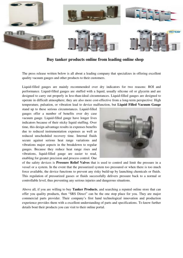
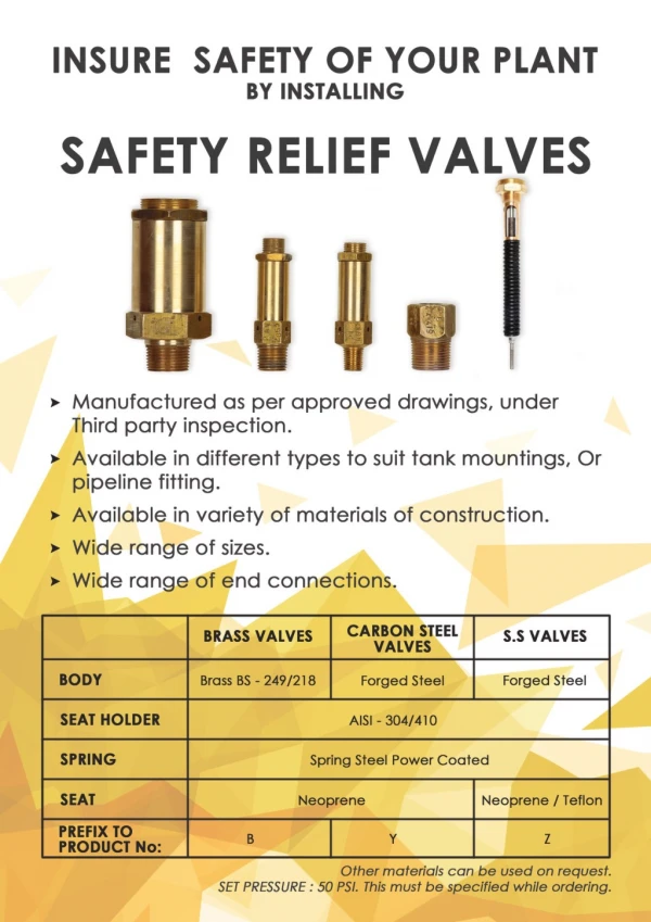
Choosing Relief Types • Spring-Operated Valves • Rupture Devices CHOOSE TYPE
Conventional Type Spring-Operated Valves CHOOSE TYPE
Picture: Conventional Relief Valve Conventional Relief Valve CHOOSE TYPE
Superimposed Back Pressure • Pressure in discharge header before valve opens • Can be constant or variable CHOOSE TYPE
Built-up Back Pressure • Pressure in discharge header due to frictional losses after valve opens • Total = Superimposed + Built-up CHOOSE TYPE
Balanced Bellows Type Spring-Operated Valves CHOOSE TYPE
Picture: Bellows Relief Valve Bellows Relief Valve CHOOSE TYPE
Pros & Cons:Conventional Valve • Advantages • Most reliable type if properly sized and operated • Versatile -- can be used in many services • Disadvantages • Relieving pressure affected by back pressure • Susceptible to chatter if built-up back pressure is too high CHOOSE TYPE
Pros & Cons:Balanced Bellows Valve • Advantages • Relieving pressure not affected by back pressure • Can handle higher built-up back pressure • Protects spring from corrosion • Disadvantages • Bellows susceptible to fatigue/rupture • May release flammables/toxics to atmosphere • Requires separate venting system CHOOSE TYPE
Rupture Devices • Rupture Disc • Rupture Pin CHOOSE TYPE
ConventionalMetal Rupture Disc CHOOSE TYPE
ConventionalRupture Pin Device CHOOSE TYPE
When to Use a Spring-Operated Valve • Losing entire contents is unacceptable • Fluids above normal boiling point • Toxic fluids • Need to avoid failing low • Return to normal operations quickly • Withstand process pressure changes, including vacuum CHOOSE TYPE
When to Use a Rupture Disc/Pin • Capital and maintenance savings • Losing the contents is not an issue • Benign service (nontoxic, non-hazardous) • Need for fast-acting device • Potential for relief valve plugging • High viscosity liquids CHOOSE TYPE
When to Use Both Types • Need a positive seal (toxic material, material balance requirements) • Protect safety valve from corrosion • System contains solids CHOOSE TYPE
Relief Event Scenarios • A description of one specific relief event • Usually each relief has more than one relief event, more than one scenario • Examples include: • Overfilling/overpressuring • Fire • Runaway reaction • Blocked lines with subsequent expansion • Developed through Process Hazard Analysis (PHA) DEVELOP SCENARIOS
An Example: Batch Reactor • Control valve on nitric acid feed line stuck open, vessel overfills • Steam regulator to jacket fails, vessel overpressures • Coolant system fails, runaway reaction DEVELOP SCENARIOS
Sizing Reliefs • Determining relief rates • Determine relief vent area SIZE RELIEFS (Single Phase)
Scenarios Drive Relief Rates • Overfill (e.g., control valve failure) • Fire • Blocked discharge • Maximum flow rate thru valve into vessel • Vaporization rate due to heat-up • Design pump flow rate SIZE RELIEFS (Single Phase)
Overfill Scenario Calcs • Determined maximum flow thru valve (i.e., blowthrough) • Liquids: • Gases: SIZE RELIEFS (Single Phase)
Fire Scenario Calcs • API 520 gives all equations for calculating fire relief rate, step-by-step • Determine the total wetted surface area • Determine the total heat absorption • Determine the rate of vapor or gas vaporized from the liquid SIZE RELIEFS (Single Phase)
Determine Wetted Area SIZE RELIEFS (Single Phase)
Determine Heat Absorption • Prompt fire-fighting & adequate drainage: • Otherwise: where Q is the heat absorption (Btu/hr) F is the environmental factor • 1.0 for a bare vessel • Smaller values for insulated vessels Awet is the wetted surface area (ft2) SIZE RELIEFS (Single Phase)
Determine Vaporization Rate where W = Mass flow, lbs/hr Q = Total heat absorption to the wetted surface, Btu/hr Hvap = Latent heat of vaporization, Btu/lb SIZE RELIEFS (Single Phase)
LiquidService where Determine Relief Vent Area • A is the computed relief area (in2) • Qv is the volumetric flow thru the relief (gpm) • Co is the discharge coefficient • Kv is the viscosity correction • Kp is the overpressure correction • Kb is the backpressure correction • (r/rref) is the specific gravity of liquid • Ps is the gauge set pressure (lbf/in2) • Pb is the gauge backpressure (lbf/in2) SIZE RELIEFS (Single Phase)
GasService where Determine Relief Vent Area • A is the computed relief area (in2) • Qm is the discharge flow thru the relief (lbm/hr) • Co is the discharge coefficient • Kb is the backpressure correction • T is the absolute temperature of the discharge (°R) • z is the compressibility factor • M is average molecular weight of gas (lbm/lb-mol) • P is maximum absolute discharge pressure (lbf/in2) • c is an isentropic expansion function SIZE RELIEFS (Single Phase)
GasService where Determine Relief Vent Area • c is an isentropic expansion function • g is heat capacity ratio for the gas • Units are as described in previous slide SIZE RELIEFS (Single Phase)
A Special Issue: Chatter • Spring relief devices require 25-30% of maximum flow capacity to maintain the valve seat in the open position • Lower flows result in chattering, caused by rapid opening and closing of the valve disc • This can lead to destruction of the device and a dangerous situation SIZE RELIEFS (Single Phase)
Chatter - Principal Causes • Valve Issues • Oversized valve • Valve handling widely differing rates • Relief System Issues • Excessive inlet pressure drop • Excessive built-up back pressure SIZE RELIEFS (Single Phase)
Worst Case Event Scenario • Worst case for each relief is the event requiring the largest relief vent area • Worst cases are a subset of the overall set of scenarios for each relief • The identification of the worst-case scenario frequently affects relief size more than the accuracy of sizing calcs CHOOSE WORST CASE
Design Relief System • Relief System is more than a safety relief valve or rupture disc, it includes: • Backup relief device(s) • Line leading to relief device(s) • Environmental conditioning of relief device • Discharge piping/headers • Blowdown drum • Condenser, flare stack, or scrubber DESIGN RELIEF SYSTEM
Installation, Inspection, and Maintenance • To undermine all the good efforts of a design crew, simply … • Improperly install relief devices • Fail to regularly inspect relief devices, or • Fail to perform needed/required maintenance on relief devices
?? Reduced Inlet Piping Reduced Inlet Piping Anything wrong here?
?? Plugged Bellows, Failed Inspection, Maintenance Anything wrong here? Signs of Maintenance Issues Bellows plugged in spite of sign Failed Inspection Program
?? Discharges Pointing Down Anything wrong here? Discharges Pointing Down Anything wrong here?
?? Long Moment Arm Long Moment Arm Anything wrong here?
?? Will these bolts hold in a relief event Will these bolts hold in a relief event? Anything wrong here?
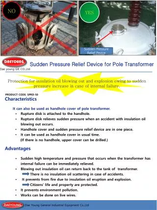
Mexico City Disaster Major Contributing Cause: Missing Safety Valve
Summary • Pressure Relief • Very Important ACTIVE safety element • Connected intimately with Process Hazard Analysis • Requires diligence in design, equipment selection, installation, inspection and maintenance • Look forward to … • Two-phase flow methodology/exercise