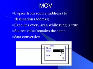
MOV Instruction
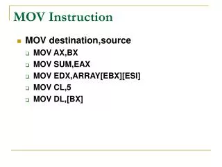
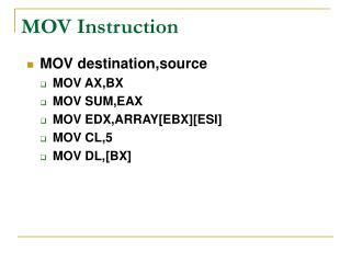
MOV Instruction. MOV destination,source MOV AX,BX MOV SUM,EAX MOV EDX,ARRAY[EBX][ESI] MOV CL,5 MOV DL,[BX]. Addressing Modes. These are the different ways in which data may be accessed by the microprocessor. Immediate. Register. Memory. Direct. Register indirect. Base plus index.

MOV Instruction
E N D
Presentation Transcript
MOV Instruction • MOV destination,source • MOV AX,BX • MOV SUM,EAX • MOV EDX,ARRAY[EBX][ESI] • MOV CL,5 • MOV DL,[BX]
Addressing Modes • These are the different ways in which data may be accessed by the microprocessor. • Immediate. • Register. • Memory. • Direct. • Register indirect. • Base plus index. • Register relative. • Base relative plus index. • Scaled indexed.
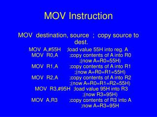
Immediate • Directly accessible to the EU. • The address is part of the instruction. • Useful in initializations. • MOV EAX,1111000B • MOV CL, 0F1H
Register • Directly accessible to the EU. • Most compact and fastest executing instructions. • Operands are encoded in the instruction. • MOV EBX,EDX • MOV AL,CL
Memory • When reading or writing to memory the execution unit passes an offset value, the effective address, to the bus interface unit which then computes the physical address.
Direct • Simplest memory addressing mode. • Direct addressing (3 bytes long). • MOV EAX,DS:SUM • MOV DS:[3000H],AL • Displacement addressing (>3 bytes long): • MOV DS:[500H],EDX • MOV CX,COUNT+5
Register Indirect • MOV EAX, DS:[EBX] • MOV DS:[EDI],EDX
Base Plus Index • Similar to register indirect. • The base registers, (BX, BP), and index registers, (DI, SI), are combined in pairs (base, index) to indirectly access data. • Any two 32 bits registers, with the exception of the ESP register, may be combined in this addressing mode for 80386 and above CPUs. • MOV DH,[BX][DI] • MOV DH,[BX+DI]
Register Relative • Access to one dimensional arrays. • MOV EAX,DS:ARRAY[EBX] • MOV DS:MESSAGE[EDI], DL
Base Relative Plus Index • Used to access two dimensional arrays or arrays contained in structures. • MOV DS:ARRAY[EBX][EDI],EAX • MOV DX, DS:ARRAY[BX+SI]
Scaled Index • The scaling factor are powers of two: 1 for byte sized data, 2 for word size, 4 for double word size… • MOV EAX,DATA[EBX][ECX*4] • MOV ARRAY[EBX+EDX*1],DL
Accessing Arrays • One dimensional arrays. • MOV DS:ARRAY[ESI*SF],EDX • SF = Scaling factor for data size. • Two dimensional arrays. • MOV DS:ARRAY[EBX*SF*SR][ESI*SF],EDX • SF = Scaling factor for data size. • SR = Size of row.
INC Instruction • INC operand • operand = operand + 1 • INC BX • INC COUNT • INC DWORD PTR [EBX]
JMP Instruction • JMP label • EIP = label • JMP AGAIN
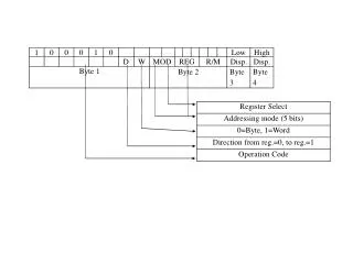
Machine Language • Native binary code that the microprocessor understand and uses as its instructions to control its operation. • Their length vary from 1 to 13 bytes. • The instructions for the 8086 through the 80286 have the format shown below.
Machine Language • The instructions for the 80386 through Pentium 4 have the format shown below.
Machine Language • The Opcode selects the operation to be performed by the microprocessor. • The remaining two bits indicate: • D – direction of flow of information: • D=0: R/M←REG; • D=1: REG←R/M. • W – Size of data: • W=0: Byte; • W=1: Word, Doubleword.
Machine Language • MOD field specifies the addressing mode for the selected instruction. • REG field indicates a register. • R/M field indicates either a register MOD=11, or a memory addressing mode.
Machine Language • MOV CL,BL • D – direction of flow of information: • D=0: R/M←REG; • D=1: REG←R/M. • W – Size of data: • W=0: Byte; • W=1: Word, Doubleword.
Machine Language • MOV TEMP[DI],DX • D=0: R/M←REG; • W=1: Word, Doubleword; • MOD=01: 8 bit displacement; • REG=010: DX • R/M=101: DS:[DI]
Immediate - Memory • When reading or writing to memory using immediate addressing mode, the programmer must specify the data size otherwise the assembler will default to the largest possible data size that processor handles. • Use the following directives: • Byte ptr. • Word ptr. • Dword ptr. • MOV DS:BYTE PTR COUNT,2H
Unconditional Transfers • JMP, CALL, RET • These instructions modify the EIP register to be: • The displacement following the instruction (label), in the case of JMP and CALL; • The address stored in the stack by the CALL instruction, in the case of RET. • Ex: • JMP Again • CALL Delay • RET
Unconditional Transfers • Short jumps also called relative jumps allows displacement distance in the range -128 to 127. SHORT directive can be used to inform the assembler of its use. • JMP SHORT AGAIN • Near jumps are similar to short jumps except for the displacement distance. Range ±32K. NEAR directive is used to inform the assembler of its use. • JMP NEAR NEXT
Unconditional Transfers • The previous two forms of jumps are used in intra-segment type transfers. • FAR jump is used for inter-segment transfers. In this case both the segment address and the offset are used. This jump allows the user to jump anywhere in memory. FAR directive is used to inform the assembler of its use. • JMP FAR NEXT_SEGMENT_PLEASE
Stack Memory Addressing • LIFO – last-in first-out data structure. • PUSH puts data on the stack. • POP removes data from the stack. • PUSH source (16 bits) • (SP) = (SP – 2) • SP + 1:SP = source
Stack Memory Addressing • POP destination (16 bits) • Destination = SP + 1:SP • (SP) = (SP + 2)
Push/Pop • PUSH source • Reg16, reg32; • Mem16, mem32; • Seg; • Imm8, imm16, imm32; • PUSHA – all 16 bit registers. • PUSHAD – all 32 bit registers. • PUSHF – flags. • PUSHFD – extended flags.
Push/Pop • POP source • Reg16, reg32; • Mem16, mem32; • Seg; • Imm8, imm16, imm32; • POPA – all 16 bit registers. • POPAD – all 32 bit registers. • POPF – flags. • POPFD – extended flags.
Stack Initialization • Load both: • The stack segment register (SS); • The stack pointer (SP).
Load-effective Address • LEA – loads a 16 or 32 bits register with the address of the data specified. • LEA EBX,ARRAY • The OFFSET directive does the same thing. • MOV EBX,OFFSET ARRAY
Load-effective Address • LDS, LES, LFS, LGS, and LSS loads a 16 or 32 bits register with an offset address and DS, ES, FS, GS, and SS with a segment address. • LDS SI,MESS
Miscellaneous Data Transfer • XCHG operand1,operand2 – exchanges the contents of operand1 and operand2. • XCHG EAX,EBX • XCHG SUM,AL • XLAT – performs direct table look-up. • AL = DS:(EBX+AL) • XLAT ASCII_TABLE or XLATB
Miscellaneous Data Transfer • These instructions tranfer information between the AL, AX, or EAX register and a port. • IN accumulator,port • OUT port,accumulator • Accumulator: AL, AX, EAX. • Port: 8-bit port address, DX.
Miscellaneous Data Transfer • MOVSX - Move and sign extend: • MOV CX,BL • MOVZX – Move and zero extend: • MOVZX EAX,DATA
Miscellaneous Data Transfer • CMOV – Conditional move: • Carry, zero, sign, overflow, and parity flags or combination of conditions. • Check table 4-19 • Ex: • CMOVB test condition C=1 and means move below. • Below and above refers to unsigned data, and less and greater to signed data.
Segment Override Prefix • Segment override prefixes can be used with almost any instruction in any addressing mode. It allows the programmer to deviate from the default segments. • MOV AX,DS:[BP]
Iteration Control • LOOP • LOOPE/LOOPZ • LOOPNE/LOOPNZ • The instructions listed above are used to conditionally and unconditionally control the number of iterations a program go through a loop.
Iteration Control • Operation of LOOP: • ECX ← ECX – 1 • If ECX ≠ 0 then EIP ← EIP + displacement • Flags are not affected.
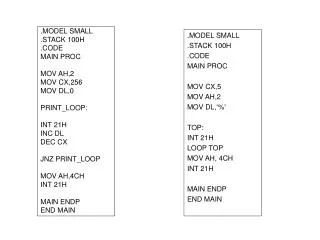
Iteration Control • Ex: • MOV ECX,2 • Again: NOP • LOOP Again • What will happen if MOV ECX,2 is replaced by MOV ECX,0 in the code given above.
Iteration Control • Operation of LOOPE/LOOPZ: • ECX ← ECX – 1 • If ZF = 1 and ECX ≠ 0 then EIP ← EIP + displacement • Flags are not affected.
Iteration Control • Operation of LOOPNE/LOOPNZ: • ECX ← ECX – 1 • If ZF = 0 and ECX ≠ 0 then EIP ← EIP + displacement • Flags are not affected. • Note that other instructions within the loop have to change the condition of ZF
Iteration Control • Ex: • MOV ECX,9 • MOV ESI, -1 • MOV AL, ‘D’ • Again: INC ESI • CMP AL, LIST[EDI] • LOOP NE Again • JNZ NOT_FOUND
Iteration Control • JECXZ/JCXZ – These instructions are conditional jumps if the ECX/CX register are equal to zero. They are used prior to a LOOP instruction to ensure that the iteration count, value in ECX/CX is never zero.


![1928tel3[1].mov](https://cdn1.slideserve.com/3422103/slide1-dt.jpg)