PETS Configuration Specifications and Cable Layout (September 2004)
This document outlines the configuration settings and cable layout for the PETS system as of September 2004. It specifies the beam orientation in three dimensions (horizontal, vertical, longitudinal), along with the precise coordinates for multiple ACEM units and their corresponding cable identifiers. Each ACEM unit is detailed with its position concerning the PETS tank entrance, ensuring accurate installation and operation. The document serves as a crucial reference for technicians and engineers involved in the setup and maintenance of the PETS system.

PETS Configuration Specifications and Cable Layout (September 2004)
E N D
Presentation Transcript
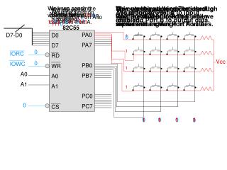
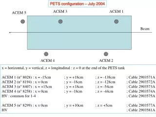
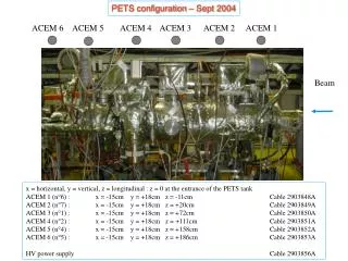
PETS configuration – Sept 2004 ACEM 6 ACEM 5 ACEM 4 ACEM 3 ACEM 2 ACEM 1 Beam x = horizontal, y = vertical, z = longitudinal : z = 0 at the entrance of the PETS tank ACEM 1 (n°6) : x = -15cm y = +18cm z = -11cm Cable 2903848A ACEM 2 (n°7) : x = -15cm y = +18cm z = +20cm Cable 2903849A ACEM 3 (n°1) : x = -15cm y = +18cm z = +72cm Cable 2903850A ACEM 4 (n°2) : x = -15cm y = +18cm z = +111cm Cable 2903851A ACEM 5 (n°4) : x = -15cm y = +18cm z = +158cm Cable 2903852A ACEM 6 (n°5) : x = -15cm y = +18cm z = +186cm Cable 2903853A HV power supply Cable 2903856A