Download
1 / 64
670 likes | 1.56k Vues
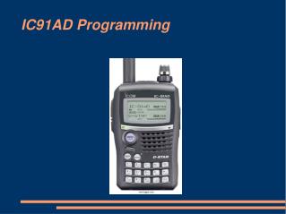
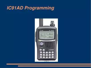
IC91AD Programming IC91AD Programming There are several ways to store information into the IC91. You can manually write channel information using the front panel. This is very tedious and error prone and not recommended unless you just want to store one or two channels.

E N D
IC91AD Programming There are several ways to store information into the IC91. You can manually write channel information using the front panel. This is very tedious and error prone and not recommended unless you just want to store one or two channels. Icom offers their copyrighted RS91 Cloning Software that uses a simple cable and PC interface. Dan Smith, KK7DS offers a free to download cloning package called CHIRP that uses the same cable as the RS91 package.
IC91AD - CHIRP http://chirp.danplanet.com/download/ Development of CHIRP is done in my spare time and is offered as open-source software, free of charge. If you like CHIRP, please consider contributing a small donation to help support the costs of development and hardware. Dan Smith KK7DS There is a PayPal link on Dan's Page.
IC91AD - Manual ProgrammingBand - A Chapter 4 in your IC91AD user manual outlines manual programming. The IC91 is divided into two bands or VFOs, A and B, or Main and Sub Band. The A Band contains 800 Memory Channels that may be divided into 26 Banks. The A Band supports FM (20 kHz. channels), WFM (Wide FM 150 kHz channels) and AM, receiving from 495 kHz to 999.990 mHz. - NOTE – NO DSTAR in the A BAND. Transmit is limited to FCC Band Allocations.
IC91AD - Manual ProgrammingBand - B The B Band contains 400 Memory Channels that may be divided into 26 Banks. The B Band supports FM (20 kHz. channels), NFM (Narrow FM 12.5 kHz. channels) AM and DV (DSTAR), receiving two segments from 118 mHz. to 174 mHz. and 370 mHz. To 470 mHz. NOTE - DSTAR is in the B BAND only. Transmit is limited to FCC Band Allocations.
IC-91 Keyboard Press buttons on the face of the IC-91 do multiple tasks. Each key has two or three different labels. The RED labels indicate pressing momentarily. The BLACK labels indicate press and hold for two seconds. The keyboard also generates DTMF or Touchtones during transmit and numeric input for frequency entry or channel number.
IC-91 Keyboard - MENU / LOCK The MAIN / DUAL key momentarily toggles between A and B Band VFOs. Press and Hold the MAIN / DUAL Key and you go from Single to Dual band reception. The MENU / LOCK key momentarily toggles between Menu and Operate modes. Press and Hold the MENU / LOCK key to LOCK the keyboard. A small KEY icon is displayed in the upper right corner of the display to indicate Key Lock.
IC-91 Keyboard - A Menu The MENU Items differ between the A and B BANDS. The MENU in the A BAND offers: 1 - SET MODE 2 - SCAN 3 - DUP / TONE 4 - DISPLAY SOUNDS The UP/DOWN/LEFT and RIGHT arrow keys are used to navigate through the menus, and the 5 Key with the ENTER sysbol is used to WRITE info.
IC-91 Keyboard - A or B BandMenus - SET MODE page 1. AP OFF - Turns the Radio OFF after a fixed time. A small clock icon is displayed in the upper right of the screen to indicate timer operation. Power Save - Momentarily powers the radio off for a short time at periodic intervals to improve battery life. Attenuator - Reduces Receive Sensitivity to reduce interference.
IC-91 Keyboard - A or B BandMenus - SET MODE page 2. Monitor - Sets the monitor key for Momentary or Toggle activation – Monitor listens to your transmit frequency. Dial Speed Up - Accelerates the rotary dial action. Auto Rpt - Automatically sets transmit offset based on the band segment and the Offset programmed in the DUP/TONE Offset menu.
IC-91 Keyboard - A or B BandMenus - SET MODE page 3. MIC Simple - Sets how the HM-175 Spk/Mic operates. Weather Alert - Causes the radio to scan the WX channel and sound alert tones when NOAA broadcasts severe weather alerts. AP ON - Automatically turns the radio ON after a fixed OFF time.
IC-91 Keyboard - A or B Band Menus - SET MODE page 4. Lock - Sets whether to lock all keys or exclude volume or squelch controls. PTT Lock - Sets whether to include PTT in the Lock setting. Busy Lockout - Prevents transmission when the radio is un-squelched or receiving a call.
IC-91 Keyboard - A or B Band Menus - SET MODE page 5. TOT – Limits Transmit ON time in the event of a stuck microphone. Active Band – Single / All - In the VFO mode, when using the channel selector to advance frequency, SINGLE keeps the VFO in one band or range of frequencies, such as the 2M band. ALL lets the VFO cross band boundaries.
IC-91 Keyboard - A or B Band Menus - SCAN - page 1. Priority Watch – ON, OFF, BELL – Interrupts calls in progress to check for calls on the PRIORITY channel and can sound an alert – Bell – when there is activity on the priority channel. Priority Watch toggles between the VFO and either a Call channel, or a Memory Channel, or Bank Scan of Memory Channels. Priority Watch works in either Band A or B, but not both at the same time.
IC-91 Keyboard - A or B Band Menus - SCAN - page 2. Pause – Sets hang time when there is activity on a channel – varies from 2 seconds up to holding for the duration of the call. Resume – Sets how long the radio will remain on a channel being scanned after the call ends. Ranges from 0 seconds to indefinite hold. Bank Link – Sets which and how many banks will be scanned.
IC-91 Keyboard - A or B Band Menus - Duplex / Tone page 1. Offset Frequency – Sets the Repeater Offset used in the 2 Meter Band. Repeater Tone – Sets the Sub Audible tone used to access a repeater. CTCSS Tone – Sets the Sub Audible tone used by the radio receiver to block interfering signals.
IC-91 Keyboard - A or B Band Menus - Duplex / Tone page 2. DTCS Code - The Digital Squelch Code used to access a digital coded squelch access repeater. DTCS Polarity – Sets whether data bits causing a positive shift in frequency are zero or one bits. DTMF Speed – Sets the duration of DTMF tones used in autopatch and control functions.
IC-91 Keyboard – A or B Band Menus - DISPLAY page 1. Backlight – ON, OFF, AUTO, On Continuously. OFF and Automatically turns on for a few seconds after changing a setting. Busy LED – ON, OFF – Indicates activity on the radio channel. LCD Contrast – Sets the screen contrast for best visibility.
IC-91 Keyboard – A or B Band Menus - DISPLAY page 2. Scan Name – ON/OFF – Displays the name of the Programmed Scan List or Bank Name. Opening LOGO – Displays ICOM IC-91 - ON/OFF. Opening Call Sign – Displays MY CALL on power up - ON/OFF. Font Size – Sets Small or Large display font.
IC-91 Keyboard – A or B Band Menus - SOUNDS page 1. Beep Level – Sets the Loudness of Beep Tones. Key Touch Beep – ON/OFF – Sets Key Touch Beep. Scan Stop Beep – ON/OFF – Sets Beep on Scan Stop
IC-91 Keyboard - A or B Band Menus - Sounds page 2. Scope AF – Turns Speaker ON/OFF during band sweep. Volume Select – Combines or Separates loudness setting for A and B Bands. Standby Beep – In DV Mode causes a beep when the sending station stops sending or the signal fades.
IC-91 Keyboard – B Band Menus 1 – Call Sign 2 – Received Call Sign 3 – Message / Position 4 – DV Voice Memo 5 – Set Mode 6 – DV Set Mode 7 – SCAN 8 – Duplex / Tone 9 – Display 10 – Sounds
IC-91 Keyboard - B Band Menuspage 1 1 - Call Sign – Sets UR, RPT1, RPT2, and MY. Allows choosing pre-programmed call signs stored in the UR or Repeater call memories. 2 - RX Call Sign – Displays a list of recently received DSTAR Call Signs.
IC-91 Keyboard – B Band Menuspage 2. 3 - Message / Position 3a - Transmit Message – Displays the 20 Character message to be sent. 3b - Received Message – Displays the Received 20 character message. 3c - GPS – Sets TX String 3d - Received GPS – Displays Received String 3e - Position – Displays MY Position and the Received Stations Position.
IC-91 Keyboard - B Band Menuspage 3. 4 - DV Voice Memo – Track 1, 2 or 3 Selects the Recording Track for recording incoming voice. Reply Voice Records and Plays Back your Auto Reply Message. Track Size sets the message length for incoming message recording. 5 - Set Mode – The SET MODE in A and B are the same and either sets BOTH.
IC-91 Keyboard – B Band MenusDV SET MODE page 1. 6 – DV Set Mode 6a – Auto Reply 6b – Digital Code 6c – DV Data Transmit 6d – Digital Monitor 6e – Digital Repeater Set 6f – Received Call Sign Write 6g – Received Repeater Call Sign Write 6h – GPS Mode – OFF / ON 6i – GPS Auto Transmit Interval 6j – Auto Detect DV Transmissions 6k – Edit Records
IC-91 Keyboard – B Band MenusDV SET MODE page 2. 6a – Auto Reply – OFF/ON/Voice. When set and your radio receives a call directed to your call sign or Digital Group Code (CSS or DCS), where UR=MY CALL, the IC-91 can be set to automatically reply with your TX Message and a short Voice Message.
IC-91 Keyboard – B Band MenusDV SET MODE page 3. 6b – Digital Code – Sets a 2 digit numerical code for selective group calling. This allows radios to remain muted until a call is directed to a specific group number or call sign. 6c – DV Data Transmit – PTT/AUTO - The 1200 baud data port on the IC-91 sends serial data interleaved with the digital voice information. This setting determines whether the data is sent on PTT or automatically.
IC-91 Keyboard – B Band MenusDV SET MODE page 4. 6d – Digital Monitor – Auto/Digital/Analog – Sets how the receiver detects signals in the DV mode when the squelch button is pressed. 6e – Digital Repeater Set – ON/OFF Automatically 'STORES' the repeater's Call Sign when your radio is not programmed correctly to your repeater's call sign.
IC-91 Keyboard – B Band MenusDV SET MODE page 5. 6f – Received Call Sign Write – OFF/AUTO – Writes the call sign of the received station to the UR field in your radio. This does not work well when two local stations are in contact with a distant station via a gateway because the local user's call sign overwrites the distant user's call sign and causes the call to be mis-routed.
IC-91 Keyboard – B Band MenusDV SET MODE page 6. 6g – Received Repeater Call Write – Temporarily saves RPT1 and RPT 2 when programmed incorrectly – Differs from Digital Repeater Set because the information is not stored to a memory. 6h – GPS Mode – ON/OFF – Enables or Disables sending the GPS Sentence and informaiton.
IC-91 Keyboard – B Band MenusDV SET MODE page 7. 6i – GPS Automatic Tranmit – Sets the time interval for automatic GPS Transmit. This can vary from OFF to 30 Minutes. When turn OFF you can still send GPS information with each manual press to talk (preferred method). 6j – Auto Detect – ON/OFF – Off detects DV only – On detects either FM or DV on a channel.
IC-91 Keyboard – B Band MenusDV SET MODE page 8. 6k – Edit Record – OFF / SELECT / AUTO – Off prevents altering channels already programmed. Select allows changing information in channels already programmed in memory, and Auto creates a new memory channel each time information is changed unless all of the memory channels are occupied, and then the radio will indicate FULL.
IC-91 Keyboard - B Band Menuspage 3. 7 - Scan - Same as A Band Menu – Affects single band only. 8 - Duplex / Tone - Same as A Band Menu 9 – Display – Same as A Band Menu – Affects both A and B bands – DSTAR features on B only. 10 – Sounds – Same as A Band Menu – Affects both A and B bands.
IC-91 Keyboard – BAND (BANK) Key page 1. In VFO Mode the BAND Key selects the desired band. In the A VFO this is, 1.6, 51, 76, 118, 137, 370, or 850 mHz. In memory mode the BAND key selects the BANK. Confusing, isn't it ? The memory recall (MR) key has two different recalls, one is the sequential channel number, and the second press displays BANK and Channel within the bank. These are access with a short press of the key.
IC-91 Keyboard – BAND (BANK) Key page 2. When you press and hold the BAND Key, rotating the channel selector will change the BAND in VFO Mode or the BANK in MR Mode. Also, single key presses of the BAND Key will advance the BAND or BANK.
IC-91 Keyboard - #1, CLR, SCOPE page 1. The #1 key is used to enter a frequency in VFO Mode or Memory number in MR Mode. The CLR Key is used to erase an entry during call sign or memory edit. Holding the # key for 1 second (short and then long beep) will cause the band scope perform a single sweep across the band and indicate the presence of signals across the band.
IC-91 Keyboard - #1, CLR, SCOPE page 2. Rotating the channel selector knob will move the center frequency of the single sweep and display the frequency of any indication on the sweep. Press VFO button to return to normal. Press and hold the #1 Key – SCOPE for 3 seconds (one long and then two short beeps) for continuous band sweep. VFO cancels the sweep.
IC-91 Keyboard - #2, UP, VFO SCAN page 1. The #2 key is used for frequency or memory channel entry. The UP ARROW is used for editing call sign or memory information. Press and Hold SCAN for 2 seconds to start scan. The CH SEL knob sets the type of scan while the SCAN button is pressed.
IC-91 Keyboard - #2, UP, VFO SCAN page 2. The type of SCAN depends on whether you start in VFO or MEMORY. In VFO your choices are ALL, BAND, PROGRAMED or DUPLEX. Press and Hold the SCAN Key while turning the Channel Selector to make your choice. Pressing the VFO Key stops scanning. ALL Scans the full range of the Band (A or B) you are using.
IC-91 Keyboard - #2, UP, VFO SCAN page 3. BAND scans within preset band limits determined by A and B (Main and Sub) bands. Programmed SCAN in the VFO Mode scan between a lower and upper frequency limit that is programmed into any of 24 different programmed scan ranges, 00A-00B to 24A-24B where A is the lower and B is the upper limit. These limits program just like Memory channels or the Call Channel.
IC-91 Keyboard - #2, UP, VFO SCAN page 4. DUPLEX SCAN toggles between send and receive frequencies in half duplex or repeater offset channels.
IC-91 Keyboard - #2, UP, MR SCAN page 1. Press MR Once. The first press displays channel numbers from 000 to 399 plus the band scan limits. Then Press and HOLD the Scan Key. Your choices are ALL, BAND, MODE and DUPLEX. Press MR a Second Time and the Bank and channel number are displayed. Your choices are ALL, BANK-LINK, BANKS, and DUPLEX. Pressing the VFO Key stops scanning.
IC-91 Keyboard - #3, A/a, LOW The #3 key is used for DTMF during Transmit, Memory Recall channel or bank channel entry, and to switch between Alpha, / and Numeric during text and call sign entry, and when you Press and Hold the #3 Key the radio toggles between Hi and Low transmit power.
IC-91 Keyboard - *, REC, MODE During Transmit This key sends the Touch Tone * Character. A short press puts the radio in the received voice record mode and lets you pick the track (Setup in DV Voice Memo) you want to record. Press REC again and the received signal will be recorded.
IC-91 Keyboard – A, VFO, mHz. This Key Sends the Touch Tone A Character during transmit. A short press switches from Memory Channels to VFO and Press and Hold this key to change the dial increment from kHz the mHz and 10's of mHz.
IC-91 Keyboard – 4, <, DUP This key sends the DTMF digit 4 during Transmit, the < key moves the cursor to the left during data or frequency entry, and pressing DUP for 2 seconds changes the send frequency from Simplex to a plus or minus offset for repeater operation.
IC-91 Keyboard – 5, ENT, SKIP The 5 key sends the DTMF digit 5 during transmit. ENT write screen contents for data entry, and pressing SKIP for 2 seconds either SKIPS a memory location, or PSKIPS a frequency in band scan.
IC-91 Keyboard – 6, >, MN The 6 key sends a DTMF digit 6 during transmit. In data entry the > moves the cursor to the right, and the MN (Memory Name) toggles between OFF, Memory Name and Bank Name when pressed for 2 seconds.