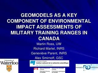
GEOMODELS AS A KEY COMPONENT OF ENVIRONMENTAL IMPACT ASSESSMENTS OF MILITARY TRAINING RANGES IN CANADA
GEOMODELS AS A KEY COMPONENT OF ENVIRONMENTAL IMPACT ASSESSMENTS OF MILITARY TRAINING RANGES IN CANADA. Martin Ross, UW Richard Martel, INRS Genevi ève Parent, INRS Alex Smirnoff, GSC. 155-mm Howitzer Round. TNT Near Ruptured 90-mm Round. M67 Hand Grenade. 2.75-in Rocket Warhead.

GEOMODELS AS A KEY COMPONENT OF ENVIRONMENTAL IMPACT ASSESSMENTS OF MILITARY TRAINING RANGES IN CANADA
E N D
Presentation Transcript
GEOMODELS AS A KEY COMPONENT OF ENVIRONMENTAL IMPACT ASSESSMENTS OF MILITARY TRAINING RANGES IN CANADA Martin Ross, UW Richard Martel, INRS Geneviève Parent, INRS Alex Smirnoff, GSC
155-mm Howitzer Round TNT Near Ruptured 90-mm Round M67 Hand Grenade 2.75-in Rocket Warhead
General problem • Environmental impact of training activities • Land use sustainability issues • Using training ranges • Maintaining base facilities • Whilelimiting the impact on the environment… • Remediation of pollutedmilitaryfacilities • Base closures, lawsuits, etc.
General objectives • Characterize the state of the environment on military training ranges • SW, GW, Soil • Aquifer vulnerability • Understand the environmental behavior of energetic materials under field conditions • Field and lab experiments • Contaminant transport, Specific vulnerability • Risk analysis • Design sustainable training methods
Geological mapping Surface and GW surveys Database development • Initial drilling phase • Water level, and sampling • surveys • Field measurements • Infiltration tests, Slug tests • Sediments • Landforms • Archival data • New data Initial 2D and 3D analyses • Subsurface analysis (cross sections, early 3D models) • Initial hydrogeologic conceptual model • Geophysics • Stratigraphic drilling • New wells, new tests Strategic subsurface investigation Advanced 3D modeling • Geological modeling • Hydrogeological modeling • Contaminant plume visualization Integrated approach
Field work Geological mapping GW sampling Subsurface sampling Well drilling Field tests
Cold Lake Air Weapons Range (AB) • - Gagetown (NB) • - Wainwright Area Training Center (AB) • - Shilo (MB) • - Petawawa (ON) • - Valcartier (QC)
3D model (WATC) Thrust mass of proglacial seds. Hummocky terrain 10 km Eskers Aeolian sand Bedrock Moraine; till N
Well Locations Wells from previous studies (30) sampled (5) INRS Wells 2003 (30) samples (25) INRS Wells 2004 (15) samples (35) INRS Wells 2005 (13) samples (53)
Semi-regular grids (prismatic cells) Irregular xy-plane mesh (Same as original surface) Regular in z Thinner cells Thicker cells
Applications Aquifer vulnerability and risk analyses
Downward advective time (DAT) method ground surface q = recharge rate m = cell thickness (vadose zone thk) n = water content water table
Land Use Management of Canadian Forces Bases using Aquifer Vulnerability and Risk Maps extent
Applications GW flow and contaminant transport modeling
Geomodel vs GW models 3D gOcad model Semi-regular grid (GridLab) “Twin” grid (GMS)
Visualisation, QA/QC… Uppermost layer
Facilitate transfer of GOCAD geomodel properties to the GMS grid Develop a tool in order to replace Access procedures Attach a simple and intuitive interface to facilitate user interaction with the tool The goal of the interface IDE (Integrated Development Environment) for Java called JBuilder
Inputs and outputs GOCAD Files with Properties GMS File with GOCAD Properties GOGMS GMS File
Interface (Java) Layer Files Management Buttons GOCAD Layer Files Panel GMS File Panel Status And Progress Bars Property Transfer Button
Summary – geomodeling approach Integrated approach / solution Software interplay / interoperability Multiple applications grid types / resolution Model building Stratigraphic repository Geologic knowledge Data gathering
Grenade ranges, • Anti-tank ranges, • Mortar/Artillery, • Air weapons ranges • Demolition ranges, • Small Arms ranges…
Typical anti-tank range • Rockets have a high misfire rate (20-40%) • Unexploded charges at the soil surface Targets (old tanks)
Slow and irregular release of EM TNT HMX No transformation, No mineralization Transformation in 2A-DNT + 4A-DNT Transported to the water table Products bind to the soil Conceptual model (vadose zone) Rockets Target Octol Soil Surface Unsaturated Zone Saturated Zone
Regional assessment Different settings Multiple objectives Gw flow system Hydrogeochemistry Aquifer vulnerability Risks (human activities) Low HQ subsurface data density Modeling near-surface and extensive units Site-specific studies Fewer settings and objectives Local GW flow Behavior of contaminants Site remediation Higher HQ data density More detailed near-surface stratigraphy Modeling internal heterogeneity? Different scales, different needs
CLAWR 110 km WATC AB SK
Hydraulic Heads in the Upper Aquifer Average Groundwater Velocity in the Upper Aquifer: ~15 m/year ? ? ?
Interoperability… • Different applications generally have different needs/requirements • Model resolution / stratigraphic details • Type of discretization • Discontinuous vs continuous units • Multiple softwares may be involved • Compatibility problem • “Software interplay”: • Time-consuming operations • Integration of errors
A streamlined process… • The Geologic Framework Model is created first • 3D grids are generated/updated semi-automatically • A series of actions is executed by a user • The “history” is saved (text file) • This file is updated and run every time the same task (e.g. building a new discretization) is needed • Run time… just enough to go get a coffee…