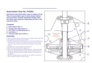
Autorotation
Autorotation. The ability to maintain and control rotor RPM in the event of an engine malfunction so controlled flight may be continued to the ground. Airflow during helicopter descent provides the necessary energy to overcome blade drag and to turn the rotor.

Autorotation
E N D
Presentation Transcript
Autorotation The ability to maintain and control rotor RPM in the event of an engine malfunction so controlled flight may be continued to the ground. Airflow during helicopter descent provides the necessary energy to overcome blade drag and to turn the rotor. The aviator gives up altitude at a controlled rate in return for the needed energy to turn the rotor at an RPM that provides aircraft control. Stated another way, the helicopter has potential energy by virtue of its altitude.
UH OH! POOF! In powered flight, rotor drag is overcome with engine power. When the engine fails, or is otherwise disengaged from the rotor system, some other force must sustain rotor RPM so controlled flight can be continued to the ground.
If a loss of power should occur with the helicopter in this condition, RPM decay is rapid. To prevent RPM decay, the collective must be lowered immediately to reduce the drag and incline the TAF vector forward toward the axis of rotation
Entry and Descent Specific entry technique may vary and will be determined by such factors as airspeed, gross weight, density altitude and altitude above the landing surface.
Entry and Descent cont.. From cruise altitudes and airspeeds, the collective must be reduced and the cyclic adjusted to achieve an airspeed that maintains RRPM while affording a reasonable glide distance and rate of descent.
Entry and Descent cont.. Once a steady state autorotation has been achieved, any movement of the cyclic will affect Rotor RPM. Aft cyclic will initially increase R-RPM and forward cyclic will reduce RRPM. R-RPM will stabilize at some other value once cyclic inputs are stopped.
Maximum Glide Distance • Best Glide Distance is determined through flight tests • The specific speed at which a power-off glide will cover the maximum distance • Typically 4 to 1 (4 feet forward for every 1 foot of descent) Or One NM per 1,500’AGL • Rotor RPM Approximately 90% • Airspeed Approximately 75 KIAS
Minimum rate of descent • For each aircraft, there is an airspeed that will result in the minimum rate of descent. • The values for minimum rate of descent are determined through flight tests. • For the R-22 - 53KIAS • Values are very close to the airspeed for minimum drag.
Driven Region 30% of radius Driving Region 45% of radius Blade regions in a vertical autorotation Stall Region 25% of radius
Stall Region • That area inboard of the 25% radius • Operates above the critical angle of attack • Contributes little vertical lift but some rotational drag
Stall Region TAF L D
Driving Region • That blade region between approximately 25% and 70% radius • Operates at comparatively high angles of attack • Resultant aerodynamic force is inclined slightly forward of axis of rotation in the direction of rotation • Inclination of the total aerodynamic force provides horizontal thrust in the direction of rotation and tends to increase RRPM
Driving Region TAF L D
Driven Region • The blade region outboard of the 70% radius • Operates at slightly less angle of attack than Driving region • Because of higher relative wind speed, provides most of the vertical lift opposing weight • Inclination provides horizontal drag, opposite the direction of rotation, which tends to decrease RRPM
Driven Region TAF L D
Driven Driving Stall Forward Autorotative regions in forward flight. Regions incline towards the retreating side
Driven Region A A Point of Equilibrium B B, D Driving Region C C Point of Equilibrium D Stall Region E E
The rotor disk TAF is tilted well forward providing the necessary thrust to propel the helicopter at the desired airspeed However, the individual blade segment TAF is inclined well aft of the axis of rotation. The engine is needed to overcome the drag forces generated by this situation.
Requirements The rotor system must be decoupled from the engine(s) This occurs if an engine malfunctions, or if the pilot retards the throttle, as in a simulated engine failure. The collective must be lowered so the angle of attack will not become so excessive that RPM will be lost.