Download
1 / 43
430 likes | 620 Vues
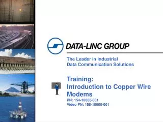
The Leader in Industrial Data Communication Solutions. Training: Introduction to Copper Wire Modems PN: 154-10000-001 Video PN: 158-10000-001. Section: Getting Started. Data-Linc Group. Industrial grade products include: Wireless Modems Ethernet Radio Modems Serial Radio Modems

E N D
The Leader in Industrial Data Communication Solutions Training: Introduction to Copper Wire Modems PN: 154-10000-001 Video PN: 158-10000-001
Data-Linc Group • Industrial grade products include: • Wireless Modems • Ethernet Radio Modems • Serial Radio Modems • Copper Wire Modems • Dial-up/Leased Line • Dedicated Wire FSK Modems • Specialty: • Analog/Discrete Multiplexers • 4-Port Switch • Accessory Devices • Factory pre-configured for your application
Modem? • Modulator – Demodulator • Used for short and long distance data communications
Duplex? • Simplex • One way communication only • Full Duplex • Simultaneous two-way communication • Half Duplex • Two way communication but one direction at any instant in time • Products that support full or half duplex inherently support simplex, which is, all our products
User Equipment Interface • Electrical Standards Supported: • RS232 • RS485 (optional) • RS422 (optional) • Data-Linc offers a wide assortment of data cables to interface your equipment to our modems
RS232 DTE and DCE • DTE: Data Terminal (PC) Equipment • DCE: Data Communications (Modem) Equipment • DTE to DCE cabling is straight through wiring
RS232 DTE Connectors • Viewed looking into the connector
RS232 DCE Connectors • Viewed looking into the connector
RS232 Voltage Levels • Voltages of -3v to -25v with respect to signal ground (DB9 pin 5, db25 pin 7) are considered logic '1' (the marking condition), whereas voltages of +3v to +25v are considered logic '0' (the spacing condition). The range of voltages between -3v and +3v is considered a transition region for which a signal state is not assigned.
RS232 Pin Functions • Clear to Send (CTS). This signal is asserted (logic '0', positive voltage) by the DCE device to inform the DTE device that transmission may begin. RTS and CTS are commonly used as handshaking signals to moderate the flow of data into the DCE device. • DCE Ready (DSR). When originating from a modem, this signal is asserted (logic '0', positive voltage) when the following three conditions are all satisfied: • 1 - The modem is connected to an active telephone line that is "off-hook";2 - The modem is in data mode, not voice or dialing mode; and3 - The modem has completed dialing or call setup functions and is generating an answer tone. • Ground. All signals are referenced to a common ground, as defined by the voltage on this pin. This conductor may or may not be connected to protective ground inside the DCE device. • Received Data (RxD). This signal is active when the device receives data. When no data is transmitted, the signal is held in the mark condition (logic '1', negative voltage). • Request to Send (RTS). This signal is asserted (logic '0', positive voltage) to prepare the DCE device for accepting transmitted data from the DTE device. Such preparation might include enabling the receive circuits, or setting up the channel direction in half-duplex applications. When the DCE is ready, it may acknowledge by asserting Clear to Send. • Received Line Signal Detector (CD) (also called carrier detect). This signal is relevant when the DCE device is a modem. It is asserted (logic '0', positive voltage) by the modem when the telephone line is "off-hook", a connection has been established, and an answer tone is being received from the remote modem. The signal is deasserted when no answer tone is being received, or when the answer tone is of inadequate quality to meet the local modem's requirements (perhaps due to a noisy channel). • Transmitted Data (TxD). This signal is active when data is transmitted. When no data is transmitted, the signal is held in the mark condition (logic '1', negative voltage).
Info: Synchronous / Asynchronous • Serialized data is not generally sent at a uniform rate through a channel. Instead, there is usually a burst of regularly spaced binary data bits followed by a pause, after which the data flow resumes. Packets of binary data are sent in this manner, possibly with variable-length pauses between packets, until the message has been fully transmitted. In order for the receiving end to know the proper moment to read individual binary bits from the channel, it must know exactly when a packet begins and how much time elapses between bits. When this timing information is known, the receiver is said to be synchronized with the transmitter, and accurate data transfer becomes possible. Failure to remain synchronized throughout a transmission will cause data to be corrupted or lost.Two basic techniques are employed to ensure correct synchronization. In synchronous systems, separate channels are used to transmit data and timing information. The timing channel transmits clock pulses to the receiver. Upon receipt of a clock pulse, the receiver reads the data channel and latches the bit value found on the channel at that moment. The data channel is not read again until the next clock pulse arrives. Because the transmitter originates both the data and the timing pulses, the receiver will read the data channel only when told to do so by the transmitter (via the clock pulse), and synchronization is guaranteed. Techniques exist to merge the timing signal with the data so that only a single channel is required. This is especially useful when synchronous transmissions are to be sent through a modem. Two methods in which a data signal is self-timed are nonreturn-to-zero and biphase Manchester coding. These both refer to methods for encoding a data stream into an electrical waveform for transmission.In asynchronous systems, a separate timing channel is not used. The transmitter and receiver must be preset in advance to an agreed-upon baud rate. A very accurate local oscillator within the receiver will then generate an internal clock signal that is equal to the transmitter's within a fraction of a percent. For the most common serial protocol, data is sent in small packets of 10 or 11 bits, eight of which constitute message information. When the channel is idle, the signal voltage corresponds to a continuous logic '1'. A data packet always begins with a logic '0' (the start bit) to signal the receiver that a transmission is starting. The start bit triggers an internal timer in the receiver that generates the needed clock pulses. Following the start bit, a fixed number of bits of message data are sent bit by bit at the agreed upon baud rate. The packet is concluded with an optional parity bit and mandatory stop bit.
Asynchronous Data Framing • Data-Linc products may support 10 and/or 11 bit words. Refer to product specification sheets • Bit count is calculated by adding the number bits composing the word • Bit count = start + data bits + parity + stop bits
Carrier Control • Two Carrier Control methods: • RTS (RS232 pin – Hardware Control) • This method places modem Tx/Rx control responsibility onto the user attached equipment. Some equipment does not provide this capability. • DSCC (Data Sense Carrier Control) • Embedded in the modem’s control logic. • Operates by monitoring received data from the user attached equipment and controls carrier automatically. • The Data-Linc LLM1100 includes DSCC.
Wire Characteristics • Unconditioned lines • Copper wire only without line compensators or signal amplifiers • Data-Linc specs use 18 gauge unshielded twisted pair in point-to-point • Conditioned • Copper wire with active and/or passive line compensators and/or signal amplifiers • No wire length restrictions • All lines require: • An analog circuit capable of passing a 1000Hz tone with loss not to exceed –16dB
2-Wire & 4-Wire Comparision • 2-wire is slightly lower cost • 4-wire provides longer wire lengths due to reduced modem loading • 4-wire offers higher throughput in half duplex networks
Private and Leased Lines • Private Line • Privately owned • Unconditioned • 2-wire and 4-wire interfaces are available • Supports point-to-point and multipoint • Leased Line • Leased from Telecom Service Provider • May be identified as VG-6 or VG-36 service • Does not provide a dial tone and dialing support • Usually conditioned • 2-wire and 4-wire interfaces are available • Supports point-to-point and multipoint • Typical multipoint Telecom Service includes line bridging
Dialup Lines • The service we use in office or home (POTS) • Always conditioned • 2-wire interface • Supports point-to-point only • SCADA equipment can sequentially dial multiple sites to achieve “polling”
Multipoint Wiring • Wiring can include any combination of star or daisy-chain connections • No termination resistors • Additional remote modems add load to unconditioned lines resulting in reduced signal strength and thus, reduced maximum line length
The Leader in Industrial Data Communication Solutions Training: Product Specific Copper Wire Modems PN: 154-10000-001 Video PN: 158-10001-001
Common Provisions • All products include: • Wall Transformer (custom input voltage available) • Users’ Guide • One Year Warrantee • Free Technical Support • Factory Configured to your specifications • Easy field re-configuration • Data cables are not included
LLM1100 • Long range communication using FSK technology • Private or leased lines • Transmits up to 20 miles (32 km) over copper wire • Supports point-to-multipoint applications • Carrier control via RTS line or automatically (DSCC) • Ideal for SCADA applications
LLM1100 Options • /B202 – Bell 202 Standard (typical) • /V.23 – CCITT V.23 Standard • /AE422 and /AE485 available • /TBLK – Two post power connector • Example: • LLM1100/V.23/AE422/TBLK
LLM1100 4-Wire Network • Note the cross- connection of wire pairs at the master
DLM4000 • Supports dial-up, 2-wire leased lines, or 2-wire private line • Point-to-point only • Advanced Trellis modulation ensures error-free data transfer • Offers error correction and compression • Factory pre-configured to your requirements • Field configurable using HyperTerminal and issuing “AT” commands • STD 9VAC power, optional 24VDC
DLM4000 Options • /DL or /LL • Dialup or Leased line. Can be changed in the field • /24V – power option of 24VDC • /422 – AE422 • /485 – AE485 • /AADB – Auto Alarm Dial Back
DLM4100 & DLM4100/ET • DLM4100-ET, Extended Temperature of –40C to +85C • Available for backplane mount in certain PLC equipment • Supports dial-up lines only • Advanced Trellis modulation ensures error-free data transfer • Offers error detection and compression • Factory pre-configured to your requirements • Field configured using HyperTerminal and issuing “AT” commands • STD 12VDC power, optional 24VDC
DLM4100 Options • /DL – Dialup, no lease line available • /ET – Extended Temperature option • /24V – 24VDC power option • -SLC, -SLC/24V –SLC/BP • Allen-Bradley SLC5/xx chassis mount • -PLC5, -PLC/24V • Allen-Bradley PLC5 chassis mount • -9030 • GE 90/30 chassis mount • -C984 • Square D Compact 984 chassis mount
MDL500-MR & MDL500-LR • High immunity to EMI/RFI • Private line only • Point-to-point and multipoint operation • Surge protection to 1500V • -MR units (2-Wire) operate up to 4 miles (6.5 km) • -LR units (4-Wire) operate up to 8 miles (13 km) • Dual channel FSK modulation for full duplex on 2-wire • STD 24VDC power • AE422 and AE485 optional
Standalone Accessories • DDM/AE485 - AE485 to RS232 Converter • DDM/AE422 - AE422 to RS232 Converter • CCDF - Carrier Control Data Flow • DSCC - Data Sense Carrier Control • WLC - Word Length Converter • REG12 – 16 to 36VDC input, 12VDC output
Startup • For each step, observe modem indicators: • Bench test modems using loopback • Bench test with your equipment • Field deploy and test again • Test slaves one by one • Missing slave test • Keep records of configurations
Troubleshooting • Clarify the symptoms • Simplify • Loopback test modems and ensure correct baudrates