CCSDS SOIS Wireless BoF
CCSDS SOIS Wireless BoF. Agenda. 1 Justification to consider OW solutions for on-board communications 2 State of the Art Review – Feedback of Optical Wireless Workshop September 2004 3 Planned Activities 4 Discussion & Conclusions (All).

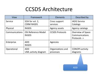
CCSDS SOIS Wireless BoF
E N D
Presentation Transcript
Agenda 1 Justification to consider OW solutions for on-board communications 2 State of the Art Review – Feedback of Optical Wireless Workshop September 2004 3 Planned Activities 4 Discussion & Conclusions (All)
1.- Reasons to consider On-board wireless communication solutions. easons to consider free-space solutions: • Reduction in the nº ofcables and connectors • Flexibility: Ease the test and integration phases • Late integration in S/C does not affect existing topology • Mechanical obstructions prohibit wired solution • Potential cost & time savings. • OPTICAL (vs. RF) •Fulfilment with S/C EMI immunity requirements • •Large unregulated bandwidth • • High miniaturization capability • …so then not only intra-S/C communications are suitable, also benefits may be provided in: • Mechanisms & Robotics mobile harness suppression • Life Science Monitoring if Human Physiological data • Test Facilities Non intrusive operations
Added value expected with the introduction of OW comms: -Availability if new functions -Greater flexibility in S/C design and construction -New design approach of Space Instruments -New possibilities for Space Missions
2.-State of the Art Review Concluded activities under different ESA Programmes: 1.-Optical Wireless Links for Intra-Satellite Communications
2.-‘Validation of a Wireless optical layer for on board data communications in an operational context’ • Goal: To review and identify an optical wireless communication system fulfilling the basic requirements of the internal data communication function of an on board control and data system and its suitability for space applications. • Specification of requirements: • -Type of communication: •Low to medium speed data (<10 Mbps) and local sensor bus —————————————————— capability. Large number of users. • • High speed data (~hundreds of Mbps) • Commercial-Off-The-Shelf Technology. • TWO CONTRACTS,TWO DIFFERENT APPROACHES: • EADS-Astrium with UPMTake the option of using ‘COTS’ IrDa standardcompliant and developing and ad hoc protocol. • -INTA with Alcatel Take the option of using COTS parts to implement a full wireless physical layer below a medium rate speed 1553 bus and a low rate ‘sensor bus type’ with adhoc (SPI based) protocol.
Presentation of ROCSAT-2: 1st application of Astrium’s Leostar bus 1.-Proposed Astrium demonstrator environment: ROCSAT (Leostar satellite family)
IPU SSR MAG OBMU GPS TWT TRSP SQPSK MTQ EPC Battery DRU Wheels Case study : ROCSAT-2
Concepts demonstrated:HW ARCHITECTURE Bus Architecture The demonstrator architecture includes the following units: • The OBC that controls the entire network. It sends the commands to equipments and receives data from them. • The AOCS and µRTUs equipments that are part of the critical platform bus. These equipments generate a low data rate (few kilobits per second). • A medium data rate payload equipment that generate data for up to 1 Mbps. • A high rate payload instrument generating up to 100 Mbps.
o - The low rate data bus architecture is a multi-points link at 115kbps using 10 receivers; 10 repeaters are also used to insure the link budget inside the spacecraft. o - The medium rate data bus architecture is a point-to-point link at physical layer level (1Mbps) o -The high rate data bus architecture is a point-to-point link with communication protocol (100Mbps) SW ARCHITECTURE
The low-rate data bus protocol decomposes the data exchanges in two parts: synchronous and asynchronous. The synchronous communication protocol allows to roughly simulate the use of standard data buses as the MIL-STD 1553B or more recently the CAN in space systems. All the data exchanges are initiated by the main calculator (master) that emits a command to a single equipment (slave) at precise times. The asynchronous communication allows to simulate the behavior of standard data buses used on ground as 802.3 (LAN) and 802.11 (Wireless LAN). All the data exchanges are initiated by the equipments. The main difference between the synchronous and asynchronous transmission lies in the collisions that can happen in the asynchronous mode.
INTA ‘s Demonstrator Configuration. OW 1553 Medium speed Netwok (1Mbps) Video camera External pay-load OW High speed Link (200 Mbps) RTU Dummy boxes OW Low-speed Network (<128Kbps) Wired sensors RTU 2-INTA’s Demonstrator
OBC (1553-BC) OBC (1553-BC) Medium-Speed Network at 1Mbps (MIL-STD1553B Protocol) RTU0 RTU1 RTU2 RTU3 Low-Speed Network at Kbps (SPI) RTU00 RTU01 RTU02 RTU30 RTU31 RTU32 RTU33 RTU10 RTU11 RTU12 RTU13 RTU20 RTU21 RTU22 RTU23 ••• + 2-INTA’s Demonstrator(ll) Demonstrator Architecture: Re-definition of hierarchy to adapt to SCI-PT-ICD-07527: High Speed Video Link: digital, >200Mbps Total 120 channels (analg.+digit)
Concepts demonstrated: • 1.-LINK CONFIGURATION • 2.- MODULATIONS • -Baseband OOK for the transmission of the Manchester coded signal of the MIL-STD-1553 (1Mbps) • -Pass-band ASK for the communication between RTU and µRTUs • 3.-MEDIUM ACCESS • -SDMA Bus MIL-STD-1553/Local bus(SPI) • -WDMA 1 RTO0 • 2 RTO1,RTO2,RTO3 • -FDMA f1, f2 ,f3 RTO1,RTO2,RTO3 • Master/Slave BC RTUs (MIL-STD-1553) • RTU µRTUs MSN:MIL-STD-1553 LSN: Local sensor bus (SPI) HSL:video transmission
3.- Planned activities in the field of Optical Wireless comms: 4.-Optical /Wireless Intra-Satellite Communications (scheduled) Taking into account the Work performed so far, the next activity is dedicated to implement an optical wireless intra-satellite communications subsystem or application in a realistic model of a satellite and prepare a flight demonstration of the selected application.