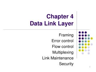
Chapter 2 A Single Segment Network -- Data Link Layer
Chapter 2 A Single Segment Network -- Data Link Layer. Data Link Layer. In this lecture, we will focus on the Data Link Layer. Main tasks of the data link layer: Transfer data from the network layer of one machine to the network layer of another machine.

Chapter 2 A Single Segment Network -- Data Link Layer
E N D
Presentation Transcript
Chapter 2 A Single Segment Network-- Data Link Layer
Data Link Layer • In this lecture, we will focus on the Data Link Layer. • Main tasks of the data link layer: • Transfer data from the network layer of one machine to the network layer of another machine. • Convert the raw bit stream of the physical layer into groups of bits (“frames”). • Perform flow control between sender and receiver. Application Layer Transport Layer Network Layer Data Link Layer Physical Layer TCP/IP Suite
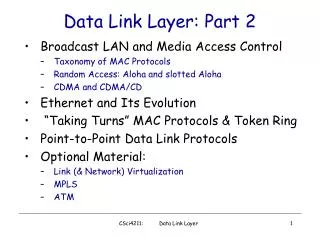
Types of Networks • Point-to-point network • Two end hosts connected by a link • Usually for long distance connections • Examples: dialup, SONET/SDH • Broadcast network • A number of stations share a common transmission medium • Local networks • Examples: Ethernet, wireless local area networks Point-to-Point Network Broadcast Network
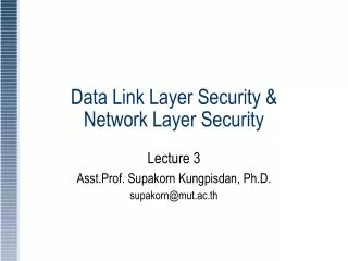
Point-to-Point Networks • The Point-to-Point Protocol (PPP) is a data link protocol. • The main purpose of PPP is encapsulation and transmission of IP datagrams, or other network layer protocol data, over a serial link. • Currently, most dial-up Internet access service are provided using PPP.
Point-to-Point Protocol (PPP) • PPP consists of two types of protocols: • Link Control Protocol (LCP) • Responsible for establishing, configuring and negotiating the data-link connection. • Network Control Protocol (NCP) • IP Control Protocol (IPCP), used for transmitting IP datagrams over a PPP link,
PPP Encapsulation • PPP frame format • Flag: mark the beginning and ending of a frame • Protocol: used to multiplex different protocol data • No addressing, only two end hosts.
Local Area Networks • Local area networks (LANs) typically connect computers within a building or a campus. • Almost all LANs are broadcast networks. • Typical topologies of LANs are bus or ring. • The protocol that determines who can transmit on a broadcast channel is called Medium Access Control (MAC) protocol. Bus LAN Ring LAN
MAC and LLC • In any broadcast network, the stations must ensure that only one station transmits at a time on the shared communication channel. • The protocol that determines who can transmit on a broadcast channel is called Medium Access Control (MAC) protocol. • The MAC protocol is implemented in the MAC sublayer which is the lower sublayer of the data link layer. • The higher portion of the data link layer is often called Logical Link Control (LLC).
LLC • LLC can provide different services to the network layer: • acknowledged connectionless service • unacknowledged connectionless service • connection-oriented service • Framing • Error control • Addressing
MAC • MAC algorithms are used to resolve collisions and share the medium in a broadcast network. • Examples of MAC: • Aloha • Carrier Sense Multiple Access/Collision Detection (CSMA/CD) • Carrier Sense Multiple Access/Collision Avoidance (CSMA/CA) • Ethernet • An industry standard since 1982 • Based on CSMA/CD.
Collisions in Ethernet • The collision resolution process of Ethernet requires that a collision is detected while a station is still transmitting. • Assume the maximum propagation delay on the bus is a. • Restrictions:Each frame should be at least twice as long as the time to detect a collision (2a).
Collisions in Ethernet t A Begins Transmission 0 A B e t +a- B Begins Transmission 0 A B t +a B Detects Collision 0 A B t +2a A detects collision just before end of transmission 0 A B
CSMA/CD • Each station listens before it transmits. • If the channel is busy, it waits until the channel goes idle, and then transmits. • If the channel is idle it transmits immediately. Continue sensing for 2a seconds. • a: the maximum end-to-end propagation delay. • If collision is detected, stop transmitting data and start to backoff. • Backoff: wait a random amount of time before attempting to retransmit.
Exponential Backoff Algorithm • If a station is involved in a collision, it waits a random amount of time before attempting a retransmission. • The random time is determined by the following algorithm: • Set “slot time” to 2a. • After first collision wait 0 or 1 time unit. • After the ith collision, wait a random number between 0 and 2 i-1 time slots. • Do not increase random number range if i>9. • Give up after 16 collisions.
Ethernet Switches • In an Ethernet LAN, hosts can be • Attached to a common cable, or • Connected by Ethernet switches. • Ethernet switches are MAC layer devices that switch frames between different ports. • Offer guaranteed bandwidth for LAN segments. • Separate a LAN into collision domains.
Ethernet Encapsulation Dest. Src. Data CRC Type Addr Addr . 4 6 6 2 46-1500 Type IP datagram 0800 2 46-1500 Type ARP request/reply PAD 0806 2 28 18 Type RARP request/reply PAD 8035 2 18 28
IEEE 802.11 Wireless LANs • Replacement for Ethernet: • wireless channel • Frequency band: unlicensed radio spectrum at 2.4GHz and 5.7GHz • Data rates: • IEEE 802.11b: 1, 2, 5.5, 11 Mbps • IEEE 802.11 a and g: 54 Mbps at 2.4GHz and 5.7GHz • Range: transmission power up to 100mW • indoor: 20 - 25 meters • outdoor: 50 - 100 meters
IEEE 802.11 Protocols • IEEE 802.11b: 5, 11Mbps • IEEE 802.11a: 6, 9, 12, 18, 24, 36, 48, 54Mbps • IEEE 802.11g: 54 Mbps • IEEE 802.11i: security • IEEE 802.11f: Inter Access Point Protocol • IEEE 802.11e: Quality of Service enhancement
IEEE 802.11 Architecture • Two working modes: • the infrastructure mode • the ad hoc mode • Fixed Access Point (AP) provides: • connection to wireline network • relay function • Handoff, an active host moves from one access point to another. • No access point. • Hosts communicate with each other directly.
Extended Service Set ESS: a set of BSSs interconnected by a distribution System • ESS and all of its stations appear to be in a single MAC layer • AP communicate with each other to forward traffic • Station mobility within an ESS is invisible to the higher layers
IEEE 802.11 MAC Layer • Priorities: • Defined through different inter frame spaces • SIFS (Short Inter Frame Spacing) • Highest priority, for ACK, CTS, Polling response • PIFS (PCF IFS) • Medium priority, for time-bounded service using PCF • DIFS(DCF, Distributed Coordination Function IFS) • Lowest priority, for asynchronous data service DIFS PIFS DIFS Medium Busy Contention Next Frame SIFS Direct access if the medium is free DIFS
IEEE 802.11 MAC Layer • A super time frame consists of Contention-free Period and Contention period. • These two periods are variable length. Their duration depends on the traffic load at the AP and at the mobile hosts. • Different channel access control schemes are used for these two periods. A Super Frame A Super Frame Contention-free Period Contention Period Contention-free Period Contention Period time
IEEE 802.11 MAC Layer • Point Coordination Function (PCF): • For delay sensitive service • Used in Contention free period • Use polling for channel access control • Distributed Coordination Function (DCF): • For best-effort data service • Use CSMA/CA for channel access control • RTS/CTS scheme is used to solve hidden-terminal problem
CSMA/CA • Why not CSMA/CD? • CSMA/CA: • CSMA: carrier sensing • Carrier: do not send • No carrier: send • Needs to be enhanced in wireless networks • CA: collision avoidance • random backoff • priority ack protocol
CSMA/CA : Backoff • Immediate access when medium is free DIFS • When medium is not free, defer until the end of current frame transmission + DIFS • To begin backoff procedure: • Choose a random number in (0, Cwindow) • Listen to determine if the channel is busy for each time slot • Decrement backoff time by one slot if channel is idle • Suspend backoff procedure if channel is busy in a time slot • Resume backoff when the channel becomes idle again.
CSMA/CA : Backoff DIFS DIFS DIFS DIFS DIFS • Cwindow: • Increases after each failure: 31, 63, 127, 255, 511, 1023, then give up • Reset to 31 after each successful transmission CWindow CWindow Frame Frame A defer Frame B defer Frame C defer Channel idle Resume backoff Frame D Channel busy suspend backoff counting Generate a random, number begin backoff Backoff counter reaches 0 and channel is idle, transmit
CSMA/CA : ACK Protocol SIFS DIFS • Receiver of directed frames returns an 14 Byte ACK immediately when CRC is correct. • If no ACK received, the sender will retransmit after a random backoff data Source ACK Dest. Contention Window Next frame Others
Z W Y X Exposed/Hidden Terminal Problems Z W Y • The exposed terminal problem • Y will not transmit to X even though it can do so • The hidden terminal problem • Y finds that medium is free and transmits a packet to W
RTS/CTS • The sender send Request-to-Send (RTS): 20bytes • Receiver returns Clear-to-Send (CTS): 14 bytes • Then transmission begins • Solves hidden terminal problem
IEEE 802.11 Frame Format • More fields than other data-link protocols • High overhead: • 30 byte header, RTC/CTS, ACK • Four Address fields: BSSID, Source Address, Destination Address, Receiving Station Address, Transmitting station Address • Different frame types for different tasks: • all fields are not present in all types of frames 0 to 2312
The Address Resolution Protocol • IP addresses are not recognizable in the interface layer where physical addresses (or MAC addresses) are used. • Different kinds of physical networks use different addressing schemes. • Address Resolution Protocol (ARP): maps an IP address to a MAC address. • Reverse Address Resolution Protocol (RARP): maps a MAC address to an IP address.
ARP Process • When a source host wants to send an IP packet to a destination, it first broadcasts an ARP request asking for the MAC address corresponding to the destination IP address. • The destination host will return an ARP reply with its MAC address.
ARP Packet Format • 28bytes long. • An ARP request or ARP reply is encapsulated in an Ethernet frame. • Protocol Type: set to 0x0806 for ARP messages. • Operation field: specifies ARP request (1), ARP reply (2), RARP request (3), or RARP reply (4).
ARP Request • Ethernet destination: ff:ff:ff:ff:ff:ff (broadcast address) • Target Ethernet Address: not set.
ARP Reply • The ARP reply is sent by the node whose IP address matches the target IP address in the ARP request. • It fills its MAC address into the target Ethernet address field of the ARP request. • It then swaps the two sender addresses (Ethernet and IP addresses) with the two target addresses, sets the op field to 2. • The ARP reply is sent back to the source host only. • All other nodes receiving the broadcast ARP ignore the request, since their IP addresses do not match the target IP address.
ARP Cache • Sending an ARP request/reply for each IP datagram is inefficient. • Each host maintains an ARP cache containing the recent resolved IP addresses. • A source host first checks it ARP cache for the destination MAC address, • If an entry is found, sends out the IP packet within an Ethernet frame. • Otherwise, sends out an ARP request.
Manipulating the ARP Table • Elements of an entry in the ARP table: • An IP address • A MAC address • Flags • A normal entry expires after 20 minutes after it is created or the last time it is referred. • Manipulate ARP table by the arp command: • arp –a: Displays all entries in the ARP table. • arp –b: Deletes an entry in the ARP table. • arp –s: Inserts an entry into the ARP table.
Proxy ARP • Hide the two physical networks from each other. • A router answers ARP requests targeted for a host.
Gratuitous ARP • Occurs when a host sends an ARP request resolving its own IP address. • Usually happens when the interface is configured at bootstrap time. • The interface uses gratuitous ARP to determine if there are other hosts using the same IP address. • The sender’s IP and MAC address are broadcast, and other hosts will insert this mapping into their ARP tables.
Loopback Interface • Most TCP implementations have a loopback interface with IP address 127.0.0.1 and namelocalhost. • The localhost behaves as a separate data link interface. • A packet that is sent to the loopback interface moves down the protocol stack and is returned back by the driver software for the localhost “device”. • Used for debugging. • Packets sent to loopback interface will not appear on network.
Network Interface Operations Functional Diagram of an Ethernet Interface Card
Maximum Transmission Unit • There is a limit on the frame size of each data link layer protocol. • This limit is called maximum transmission unit (MTU). • MTUs for various data link layers: • Ethernet: 1500 • FDDI: 4352
ICMP • The Internet Control Message Protocol (ICMP)is the protocol used for error and control messages in the Internet. • ICMP provides an error reporting mechanism of routers to the sources. • All ICMP packets are encapsulated as IP datagrams. • The packet format is simple:
Types of ICMP Packets • Many ICMP packet types exist, each with its own format.
ICMP Message Types • ICMP messages are either query messages or error messages. • ICMP query messages: • Echo request / Echo reply • Router advertisement / Router solicitation • Timestamp request / Timestamp reply • Address mask request / Address mask reply • ICMP error messages: • Host unreachable • Source quench • Time exceeded • Parameter problem
ICMP Error Messages • Each ICMP error message contains the header and at least the first 8 bytes of the IP datagram payload that triggered the error message. • To prevent that too many ICMP messages, ICMP error messages are not sent • for multiple fragments of the same IP datagrams • in response to an error message • in response to a broadcast packet
ICMP Error Message Types • There are 16 different ICMP error messages (‘codes’) of type “Destination Unreachable” (Type = 3) Code Message Type 8 Source host isolated 9 Destination network administratively prohibited 10 Destination host administratively prohibited 11 Network unreachable for TOS 12 Host unreachable for TOS 13 Communication administra- tively prohibited by filtering 14 host precedence violation 15 precedence cutoff in effect Code Message Type 0 Network unreachable 1 Host unreachable 2 Protocol unreachable 3 Port unreachable 4 Fragmentation needed but bit not set 5 Source route failed 6 Destination network unknown 7 Destination node unknown
ICMP Port Unreachable • If, in the destination host, the IP module cannot deliver the datagram because the indicated protocol module or process port is not active, the destination host may send a port unreachable message to the source host. Request a serviceat a port No. 1234 Client Server No process is waiting at Port 1234 Port unreachable
PING • PING (Packet InterNet Gopher) is a program that utilizes the ICMP echo request and echo reply messages. • PING is used to verify if a certain host is up and running. It is used extensively for fault isolation in IP networks. • PING can be used with a wide variety of options.
Echo Request and Reply • Ping’s are handled directly by the kernel. • Each Ping is translated into an ICMP Echo Request. • The Ping’ed host responds with an ICMP Echo Reply. Host 2 Host 1 ICMP ECHO REQUEST ICMP ECHO REPLY