
10”
8”. 8”. 10”. 8”. Secondary Loop. 6”. 8”. 8”. 6”. 8”. 8”. 8”. Primary Pumps. 8”. 8”. 10”. To chiller #2. 6”. 6”. To chiller #3. From Chiller #1. 8”. 6”. EXISTING CHILLER #3 EVAP. TRANE CENTRAVAC- 300Ton EXISTING CHILLER #3 CHILLED WATER PIPING ISOMETRIC DIAGRAM

10”
E N D
Presentation Transcript
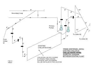
8” 8” 10” 8” Secondary Loop 6” 8” 8” 6” 8” 8” 8” Primary Pumps 8” 8” 10” To chiller #2 6” 6” To chiller #3 From Chiller #1 8” 6” EXISTING CHILLER #3 EVAP TRANE CENTRAVAC- 300Ton EXISTING CHILLER #3 CHILLED WATER PIPING ISOMETRIC DIAGRAM BETHESDA CENTRAL PLANT 6” 6” CHILLER WILL BE SITE-CLEARED BY OTHERS- FREE-COOLING SYSTEM W/ HEAT EXCHANGER WILL BE INSTALLED IN THIS LOCATION 7/29/10 TRENT
Return to Marley cooling towers 10” 6” 10” 10” from CT Pumps 6” From new 400 Ton Chiller 8” CHILLER #3 COND 8” 6” 6” TRANE CENTRAVAC-300Ton EXISTING CHILLER #3 COOLING TOWER WATER PIPING ISOMETRIC DIAGRAM BETHESDA CENTRAL PLANT 8” From new 400 T Chiller by others 6” CHILLER WILL BE SITE-CLEARED BY OTHERS- FREE-COOLING SYSTEM W/ HEAT EXCHANGER WILL BE INSTALLED IN THIS LOCATION 7/29/10 TRENT
30 HP CHW Circ Pump CURRENT 300 TON CHILLER PAD-3” Deep Chilled Water Return Chilled Water Supply – must be 8” service from 8” header above 8” Return Source must be From 8” header above 8” Future Expansion HEAT- EXCHANGER 8” 60” 8” 8” 8” 143” Plate & Frame Heat Exchanger Assembly ( Insulation & jacketed in the field) Cooling Tower Supply & Return Service must be tapped From 8” headers above FUTURE 400 TON CHILLER PAD-3”Deep (In place for Install) 30 HP CT Circ Pump 92” 175” PROPOSED FREE-COOLING SYSTEM PLAN VIEW BETHESDA CENTRAL PLANT 7/29/10 TRENT
TO HOSPITAL 10” 10” 10” 10” 10” 10” SECONDARY LOOP 10” 10” 10” RUHRPUMPEN IMP 9.55” 1200 GPM AT 60’HD 25HP 1800 RPM IR 6X9 SB IMP 8.582” 1350 GPM 30HP 1775 RPM 8” BG 1510 6BC 9.375” 1875 GPM AT 65’HD 40 HP 1775 RPM 8” 8” 10” FREE COOL SYSTEM 8” 8” CHILLER#2 400T 10” 6” 6” NEW CHILLER #3-300T 10” 8” 8” 8” 8” FROM HOSPITAL CHILLER #1- 400T CHILLER SYSTEM WITH FREE-COOLING PROVISION CHILLED WATER FLOW DIAGRAM TO HOSPITAL 8” 7/29/10 TRENT
CHILLER SYSTEM WITH FREE-COOLING PROVISION COOLING TOWER WATER FLOW DIAGRAM CHILLER #2 PENDING REPLACEMENT WITH EVAPCO USS-212-524 TYP 2 BG 1510 6BC 8.75” 1800 GPM AT 50’HD 30 HP 1775 RPM TOWER SET #1 MARLEY 8” FREE COOL SYSTEM BG 1510 6BC 9.375” 1875 GPM AT 65’HD 40 HP 1775 RPM 8” CHILLER #3 TOWER SET #2 EVAPCO TYP 2 SST-112-612 CHILLER #1 7/29/10 TRENT
Source at PRV Station Discharge below in BR 15# Steam Service CV Condensate Return 2” CV For Each 2 Heater Circuit 3” 2” 2 Tubular Steam Heating Coils Typical for each tower basin 2” All other Piping Sch 40 CS Screwed 2” 2” 2” 2” Tower Service Piping 2” 2” CV T T T Roof edge 25’ 40’ All Piping in Basin Sch 10 304/316 SS Sump Drain 25’ 23’ Sump Drain CT Basin CT Basin Roof edge All Specialities Trap/Strainer/ Valves For Each Tube Bundle Existing Evapco Towers Existing Marley Towers (dotted) New Evapco Towers to be installed soon by Owner PLAN VIEW OF ROOF CHILLER PLANT W/ CONCRETE TOWER BASINS 7/29/10 TRENT Parking Lot