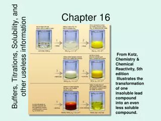
Chapter 16
Chapter 16. Additional Op-Amp Applications. Comparators. Comparator – A circuit used to compare two voltages. Comparators are typically used in conjunction with digital circuits. A digital circuit is one designed to respond to alternating dc voltage levels. Comparator Operation.

Chapter 16
E N D
Presentation Transcript
Chapter 16 Additional Op-Amp Applications
Comparators • Comparator – A circuit used to compare two voltages. • Comparators are typically used in conjunction with digital circuits. • A digital circuit is one designed to respond to alternating dc voltage levels.
Level Detector • Level detector – Another name for a comparator used to compare an input voltage to a fixed dc reference voltage.
Integrators • Integrator – A circuit whose output is proportional to the area of the input waveform.
RC Integrator • An ideal RC integrator would produce the triangular (ramp) waveform. • The practical RC integrator produces the exponential waveform.
Op-Amp Integrator • The op-amp provides a constant-current source for the capacitor, causing it to charge at a linear rate.
Differentiators • Differentiator – A circuit whose output is proportional to the rate of change of its input signal.
Summing Amplifiers • Summing amplifier – An op-amp circuit that produces an output proportional to the sum of its input voltages.
General-Class Equation • General-class equation – An equation derived for a summing amplifier that is used to predict the circuit output for any combination of input voltages. • Determine the Rf / R ratio for each branch. • Represent each branch as the product of its resistance ratio and input voltage. • Write the equation as the sum of these products.
Digital-to-Analog (D/A) Converter • Digital-to-analog (D/A) converter – A circuit that converts digital circuit outputs to equivalent analog voltages.
Averaging Amplifier • Averaging amplifier – A summing amplifier that provides an output proportional to the average of the input voltages.
Difference Amplifier • Difference amplifier – A summing amplifier that provides an output proportional to the difference between two input voltages. Also called a subtractor.
Instrumentation Amplifiers • Instrumentation amplifier – A circuit used to amplify low-level signals in process control and measurement applications.
Audio Amplifier • Audio amplifier – The final audio stage in communications receivers, used to drive the speakers.
Voltage-Controlled Current Source • Voltage-controlled current source – A circuit with a constant-current output controlled by the circuit input voltage.
Precision Rectifier • Precision rectifier – A clipper that consists of a diode and an op-amp. The circuit can clip extremely low-level input signals.