Minor Connectors
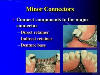
Minor Connectors. Connect components to the major connector Direct retainer Indirect retainer Denture base. Functions of Minor Connectors. Unification and rigidity Stress distribution Bracing through contact with guiding planes Maintain a path of insertion. Types of Minor Connectors.

Minor Connectors
E N D
Presentation Transcript
Minor Connectors • Connect components to the major connector • Direct retainer • Indirect retainer • Denture base
Functions of Minor Connectors • Unification and rigidity • Stress distribution • Bracing through contact with guiding planes • Maintain a path of insertion
Types of Minor Connectors • Embrasure Minor Connectors • Between two adjacent teeth
Types of Minor Connectors • Embrasure Minor Connectors • Triangular shaped in cross section • Joins major connector at right angles • Relief placed so connector not directly on soft tissue
Types of Minor Connectors • Embrasure Minor Connectors • Contact teeth above height of contour • Prevents wedging & tooth mobility • Alternatively, difficult to seat
Gridwork Minor Connectors • Connect the denture base and teeth to the major connector
Gridwork Minor Connectors • Adjacent edentulous spaces • Usually connect major connector to direct retainers • Open lattice work or mesh types
Gridwork Minor Connectors • Mesh type • Flatter • Potentially more rigid • Less retention for acrylic if openings are small
Gridwork Minor Connectors • Lattice Type • Potentially superior retention • Interferes with setting of teeth, if struts are too thick • Both types are acceptable if correctly designed
Gridwork Relief • Mechanical retention of denture base resin • Allows the acrylic resin to flow under the gridwork
Gridwork Relief • Relief wax is placed in the edentulous areas • 1 mm of relief
Relief Under the Gridwork • Should begin 1.5 - 2 mm from the abutment tooth
Relief Under the Gridwork • Creates a metal to tissue contact adjacent tooth • Preferable since it wears less • Less porous, (hygiene)
Junction With Major Connector • Butt joint with slight undercut in metal • Maximum bulk of the acrylic resin • Prevents thin, weak edges fracturing
Mandibular Gridwork Design • Extend 2/3 of the way from abutment tooth to retromolar pad • Never on the ascending portion of the ridge Stewart's, Fig. 2-55
Maxillary Gridwork Design • Gridwork • 2/3 of the length of from abutment to the hamular notch • Major connector • extends fully to the hamular notch
Gridwork Design Facially just over the crest of the residual ridge
Position of Major Connector Junction • Should be ≈ 2 mm medial to lingual surface of denture teeth • Ensures bulk of resin around teeth
Mandibular Tissue Stops • Contact of metal with cast at posterior of distal extension gridwork • Prevents distortion at free end during hydraulic pressure of processing
No Tissue Stops In Maxilla • Maxillary major connector acts as a tissue stop (no relief)
Proximal Plates • Minor connectors originating from the gridwork in an edentulous area • Broad contact with guiding planes • May or may not terminate in an occlusal rest
Proximal Plates • Shifted slightly lingually • Increases rigidity • Enhances reciprocation • Improves esthetics • Often a triangular space below the guiding plane (an undercut)
Proximal Plates • Rigid, cannot be placed in undercut • Block-out placed in undercuts prior to waxing and casting the framework
Zero Degree Block-Out • Does not deviate from path of insertion • Instructions to the laboratory should state “Use zero degree blockout”