Download
1 / 90
930 likes | 1.43k Vues
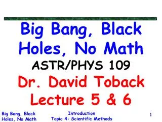
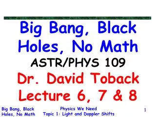
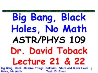
Charles Coulomb. Electrostatics – magnetism - electricity – electromagnetism. 2000 BC. 700 BC. 1600. 1785. 1819. 1831. 1873. 1888. 1909. 2004. William Gilbert Shows electrostatics occurs generally. Hans Oersted Deflects compass by electricity. James Clark Maxwell

E N D
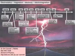
Charles Coulomb Electrostatics – magnetism - electricity – electromagnetism 2000 BC 700 BC 1600 1785 1819 1831 1873 1888 1909 2004 William Gilbert Shows electrostatics occurs generally Hans Oersted Deflects compass by electricity James Clark Maxwell Maxwell’s Equations EM waves with v = c Robert Millikan Q = Ne Chinese document magnetism Heinrich Herz Verifies ME by experiment New results Active research and applications Ancient Greeks Static electricity Elektron (Amber) Ancient Greeks Magnetism Magnetite found in Magnesia district Michael Faraday and Joseph Henry Induction of current by relative motion of magnet and conductor Dr SH Connell (76826) 082 945-7508 School of Physics, http:www.src.wits.ac.za/~connell
Electrostatics (9 lectures) Charges Insulators and Conductors 23-1,2 Coulomb’s Law 23-3 Electric Field and its calculation 23-4,5 Lines of force 23-6 Electric flux, Gauss’s theorem and applications 24-1,2,3,4 Electric Potential and potential difference 25-1 Relation between electric potential and field (1D) 25-2 Equipotential surfaces 25-1,6 Electron volt as a unit of energy 25-1 Electric potential of a point charge and charge distributions 25-3 Van de Graaff generator 25-8 Definition of capacitance 26-1 Parallel plate cylindrical capacitors 26-2 Capacitors in series and parallel 26-3 Energy of a charged capacitor 26-4 Current Electricity (7 lectures) Electric current, current density 27-1 Drift velocity and microscopic view of currrent 27-2 Ohm’s Law and resistance 27-2 Resistivity and conductivity; temperature variation 27-4 Electric Power 27-6 Resistors in series and parallel 28-2 Emf and terminal voltage 28-1 Kirchoff’s laws and their applications 28-3 Ammeters and voltmeters, determination of resistance 28-5 Wheatstone bridge and slidewire bridge 28-5
Electrostatics is an active field …………………………
“Stationary” charges Insulators Forces fields Potential Energy Capacitance STATIC ELECTRICITY Moving charges Conductors (semiconductors) Batteries & circuits Energy conversion Resistance CURRENT ELECTRICITY Due to currents (magnetic materials) Forces fields Generate currents Inductance ELECTRO- MAGNETISM
Shell model of the Atom • small +vely charged nucleus • surrounded by e- in planetary orbits • normal atom is neutral +ve nucleus N protons Charge = +Ze nuclear diameter 10-15 m (Rutherford’s exp) Electron charge -e N electrons Charge = -Ze Atomic diameter 10-10m (Einstein’s analysis of Brownian Motion) The atom is mostly empty space
The Basics (Serway 23-1,2,3,4,5,6) How do we know about static electricity ? Make sense of experiments ……. • Insulators can be charged by conduction • Conductors can be charged by induction • There are two types of charges • Like charges repel • Unlike charges attract • Benjamin Franklyn’s convention, when rubbed with fur • Glass acquires a +ve charge • Rubber acquires a –ve charge • Charge is conserved (not created or destroyed) • Charging results from separation and transferal of charges • Definition of chargeMKS/SI unit of charge is the Coulomb (C)The charge that results from a flow of currentof 1 Amp for 1 second. • Charge is quantised, q = Ne, e = 1.602 x 10⁻¹⁹ C • Materials come in three types • Conductors (Charge moves freely : Cu, Al, ….) • Insulators (Charge is not mobile : glass, rubber …) • Semiconductors (Intermediate behaviour, Si, Ge …)
Triboelectric series + Rabbits fur Glass Mica Wool Cats fur Silk Cotton Wood Amber Resins Metals (Cu, Ni, Co, Ag, etc) Sulphur Metals (Pt, Au, etc) Celluloid When two materials are rubbed against each other, the one higher in the chart will lose electrons _
There are two types of charges, positive and negative • Like charges repel, Unlike charges attract
Neutral metal sphere Charging by induction Remove ground connection Induced redistribution of charge NB : No contact ! Partial discharge by grounding Excess charge remains
A charged object induces near-surface charge in an insulator Atoms or Molecules near the surface are induced to become partial temporary dipoles This is the mechanism by which the comb attracts the paper
Coulomb’s Torsion Balance Coulomb’s Law • Coulomb showed experimentally that the electric force • between two stationary charged particles is • Inversely proportional to the square of the separation of thecharged particles and directed along the line joining them • Directly proportional to the product of the two charges. • Attractive for unlike charges and repulsive for like charges. If F is in Newtons, q1 and q2 in Coulombs and r in meters, then, e0 = permittivity of free space = 8.86 x 10⁻¹² C2N-1m-2 or Farads.m-1 then k = 1/4pe0 = 9 x 10⁹ mF-1 Twist measures repulsive force
The resultant force in a system of many charges Force is a vector quantity. The force between two charges is +q1 -q2 q1q2 < 0 attractive force and attractive (repulsive) for an overall -ve (+ve) sign. The Principle of Superposition If there are more than two point charges, then Coulomb’s Law holds for every pair of charges. Let the charges be q1, q2, q3, q4, … qn, …. Then the resultant force on qn is given by the vector sum See Examples …….
Coulomb’s Law – example 1 Find the resultant force (and direction) on q1 y q3 = -2.0 mC 10 cm 30° q2 = +3.0 mC q1 = -1.0 mC x 15 cm
v e r F +Ze The Hydrogen Atom Compare the electrostatic and gravitational the forces (The average separation of the electron and proton r = 5.3 x 10⁻¹¹ m ≈ ½ Å) Fe/Fg = 2 x 1039 The force of gravity is much weaker than the electrostatic force What other fundamental differences are there ?
Coulomb’s Law – example 2 A certain charge Q is to be divided into two parts, q and Q-q. What is the relationship of q to Q if the two charges, placed a given distance apart, are to have a maximum coulomb repulsion ?
The Electric Field The electric field E at a point in space is defined as the electric force F, acting on a positive test charge q0, placed at that point divided by the magnitude of the charge. Units NC-1 or Vm-1 It follows that • Note that the electric field E is produced by some other charge external to the test charge q0. • The existence of an electric field is a property of its source • Every charge comes with its own electric field. • The electric field will exist regardless of its magnitude and directionbeing measured with a test charge.
Electric field lines • These are a way of visualizing the electric field. • The electric field vector E is tangential to the electric field line at any point. • The magnitude of the electric field vector E is proportional to the density of the lines. • Electric field lines can never cross. • For a positive point charge, the lines are directed radialy outward. • For a negative point charge, the lines are directed radialy inward. • An electric dipole has two nearby point charges of equal magnitude q and opposite sign, separated by a distance d. The number of lines leaving the positive charge equals the number of lines entering the negative charge.
The electric field lines of two neighbouring positive point charges is as shown in the figure. At large distances, they will approximate the electric field lines a a single point charge of magnitude 2q. Example 3 Show that the density of electric field lines around a point charge is consistent with the expression for the electric field arising from Coulomb’s Law.
Calculating the Electric Field due to a point charge at a distance r Place a point charge q0 a distance r from the charge q F r + + q q0 Now calculate the electric field from the definition The unit vector r lies along the line joining the point charge and the test charge, with a direction indicating the direction the point charge would move. For the electric field due to a system of point charges, calculate the electric field vectors individually, and add them vectorially using the Principle of Superposition.
The electric field on the axis of an electric dipole Consider the situation as shown in the figure, with y >> a. The dipole moment is defined as p = 2aq The magnitudes of the electric field contributions from each charge at point P are the same. The y-components are equal, so the resultant field is ...
The Electric Field due to a continuous charge distribution Divide the continuous charge distribution into a large number of small charge elements dq and calculate the (vectorial) field dE due to each (considered as a point charge). The resultant field is found by integration
The Electric Field on the axis of a charged straight rod (line of charge) There is a charge per unit length of l, so dq = ldx and q = ll. Note y-components cancel
The Electric Field on the axis of charged ring The resultant field on axis must have no perpendicular component – by symmetry. The charge element is
The cathode ray tube This device is used to display electronic information from oscilloscopes, radar systems, television receivers and computer monitors. An electron beam is produced by an electron gun, which consists of a biased hot filament together with intensity control, acceleration and focusing electrodes. The monoenergetic electron beam (usually a few keV of energy) will strike the screen producing a luminous point at a location determined by the electric field of parallel deflection plates, arranged to control both the x and the y deflection of the beam. The signals on the electrodes of the x and y deflection plates, as well as the intensity control electrode, determine the image that is visualised.
The flux of E (Serway 24.1-24.4) We can imagine drawing electric field lines so that the number of lines per unit area perpendicular to the field is proportional to the field strength. Flux density : The number of field lines per unit area, perpendicular to the field direction (a vector quantity). This quantity is proportional to Electric field strength E. Flux (symbol FE) : is the total number of field lines passing through a particular area (a scalar quantity). It follows ….
q E Area elements We assumed a uniform E field and a flat area in the previous discussion. If we take an infinitesimally small area element, then locally, the field will be uniform and the area element flat. The flux through this area element (number of field lines through this area element) is …. An area element is therefore a vector with an orientation of its surface normal and a magnitude of its area. (Actually, the orientation could also be the opposite direction. This is explained later.) Total flux through a finite surface Integrate the infinitesimal contributions … (example of a surface integral of a vector field)
Gauss’s Law The total outward flux passing through a closed surface (Gaussian Surface) is equal to q/e0, where q is the net charge enclosed by the surface. Example : Find E at a distance r from a point charge. By symmetry, E is constant in magnitude over the gaussian surface, and E is parallel to dA z E r +q y Choose a spherical gaussian surface centered on the charge x Now, the electrostatic force is Gauss’s law is consistent with Coulomb’s Law
Note : The orientation of the vectorial area element is always outwards by convention for a closed surface Note : The presence of outside charges has no effect on the total flux passing though the gaussian surface. Inward flux is (-ve), outward flux is (+ve). +q Gaussian surface Note : Under conditions of symmetry, Gauss’s Theorem is extremely powerful, allowing conclusions to be drawn and solutions to be calculated very efficiently.
x + E + + + + + E + l + x + + + + • E near a charged straight wire • The wire has a charge l per unit length, so the charge element is dq = ldl and q=ll. • Choose a cylindrical gaussian surface placed symmetrically about the wire. • By symmetry, the field is the same in magnitude over the curved surface and Eand dA point radially outward, i.e. the angle between them is zero. • There is no flux through the top and bottom of the cylinder. Plan view gaussian surface
E near a charged isolated conductor, any shape. • There is no further motion of charge within the conductor once equilibration has been attained, in an isolated conductor. • Hence there is no field inside the conductor (otherwise free electrons would move, F = qE). • Also, E must be perpendicular to the surface, as there can be no component of E lying in the surface. charged isolated conductor gaussian surface • Choose a gaussian surface just under the charged conductor surface as shown. • Since E is zero inside, fE=0 for this gaussian surface. Hence by Gauss’s Theorem, there is no charge within the gaussian surface. • If an isolated conductor is charged, then all the charge is on the outside of the conductor
+ + + + + + + + + + + + + + + + + + + + + + + + + + + + + + + + + E near the surface of a charged conductor Surface charge density s Choose a cylindrical gaussian surface perpendicular to the charged conductor and intersecting its surface as shown. The charge element is dq = sdA (s = charge/unit area) and q = sA. g.s. E + + + + + + + + + A E = 0 E┴ surface & E = 0 inside the conductor. So all the flux is through the surface A. Note … for a thin sheet insulator
Hollow conductors (Electrostatic shields) + For a gaussian surface inside a hollow charged conductor, fE = 0, since there is no charge inside the g.s. Therefore E = 0 (No field inside a hollow conductor) A hollow conductor is an electrostatic shield, even if it is full of holes. (Faraday Cage) + + g.s. + + + + + + + + + + + + +
Electric Potential and potential difference (Serway 25-1,2,3,6,8) If the work done by an external agent in moving a charge +q0 from point A to point B is WAB, then the potential difference between points A and B (the potential at point B w.r.t. the point A) is defined as Ending at point B, starting at point A Ending at point A, starting at point B Note • If WAB is +ve, then B is at a higher potential than A. • Units are work/charge = joule/coulomb ≡ volt (V). • Potential difference is a scalar quantity • Potential energy refers to a charge-field system (work done to introduce a charge to a field). Electric potential is a scalar characteristic of an electric field, independent of any other charges. • WABdepends only the endpoints, not the path. Therefore the E-field is a conservative field. • If we take point A to be at infinity, then it will feel no E-field and we set the potential here to be zero. Work done in bringing q0 in from infinity to B. So VBis the work done per unit charge to bring a positive test charge to point B
Electric potential and electric field The work done by an external agent in moving a charge +q0 from point A to point B is WAB,. (This would be the negative of the work done by the field on the charge.) Therefore, Similarly, From the above definitions we see,
Eis parallel to dl, A is at a higher potential than B. Eis anti-parallel to dl, A is at a lower potential than B. A A + + E E + + B B For a uniform field, Consider two cases …. So, VBA is positive (negative) when B is at a higher (lower) potential than A The change in potential energy ….. So a positive charge loses potential energy when it moves in the direction of the field.
E C s A B Equipotential surfaces In the figure, points B and C are at the same potential. Points B and C therefore lie on an equipotential surface Equipotential Surface : Any surface consisting of a continuous distribution of points having the same electric potential. An equipotential surface is perpendicular to the lines of electric field. Energy unit the electron volt The electron volt (eV) : The energy an electron (or proton) gains or loses by moving through a potential difference of 1 volt. Example : An electron in a TV tube has a velocity v = 3.5x10⁷ m/s which is a kinetic energy of Ek = ½mv2 = 5.6x10⁻¹⁶ J which is equivalent to 3.5x10³ eV. This corresponds to the electron being accelerated from rest through a potential difference of 3.5 kV.
q P dl E X=∞ X=0 r The potential at a distance r from a point charge q We can choose a straight line integral path (since the potential is path independent) dx = -dl In general
The potential on the axis of a dipole Since the two charges are in magnitude but opposite in sign, the potential on the axis of the dipole must be zero, although there is an electric field. (Explain) V=0 +q -q - + The potential of any number of point charges Calculate the potential for each charge separately and add them together. VTot = + V1 + V2 + V3 + ….
Equipotential surfaces for the point charge and the dipole equipotential surface E-field line No work is done when moving a charge along an equipotential surface
Example 4 : Energy and potential A 100 eV electron is fired directly towards a metal plate that has a surface charge density of -200 nCm-2. From what distance must the electron be fired if it should just reach the plate ? Example 5 : Energy and potential Two electrons are stationery when 0.05 cm apart. They are allowed to move apart under the influence of their mutual repulsion. What are the velocity and energy in electron volts of each electron when they are 1cm apart ? Example 5 : Energy and potential A beam of alpha particles accelerated from rest through a potential difference of 2.6 x 10⁶ V in a vacuum is scattered from a fixed gold target a large distance away. Very occasionally an alpha particle collides head on with a gold nucleus and is scattered straight back. Calculate the distance of the alpha particle’s closest approach to the gold nucleus, assumed to be stationery (neglect recoil) ?
Applications of Electrostatics Van de Graaff Generator Electrical breakdown of the air due to corona discharge occurs at a field Emax Emax= 3 x 10⁶ Vm-1, so if we want Vmax = 1 x 10⁶ V, then Note :E (and s) are more concentrated where r is small – especially at sharp points Applications ….
Electro-static precipitator A corona discharge is induced in a column by applying a high voltage (40 – 100 kV) between a co-axial wire and the walls of the column. As air with particulates passes up the column, the particulates acquire a negative charge due to interactions with the corona discharge. These particulates are the extracted from the flow electro statically and they collect on the walls of the column. Without precipitators With precipitators
- + Definition of capacitance (Serway 26-1,2,3,4) Two conductors, connected to the terminals of a battery, will acquire equal and opposite charges +Q and -Q, even if the conductors are not of the same size, since a charge Q will flow through the battery. The potential difference between the conductors will be equal to V, the terminal voltage of the battery. -Q +Q Experimentally for such a system, V The constant C is called the capacitance and depends on the geometry of the system, For simple cases, we can calculate the capacitance. We will do this for two simple cases …. parallel plate capacitors and cylindrical capacitors,
1 micro farad (mF) = 10-6 F 1 pico farad (pF) = 10-12 F Since the concept of capacitance involves potential difference, there are allways two parts to a capacitive system. • Method of calculation of capacitance • Assume charges +Q and -Q are on the system. • Calculate the E-field between the two parts of the system using Gauss’s Theorem, or other method. • Calculate the potential difference between the two parts using • Find C from
+ - + - + - + - - + - + - + + - + - - + - + Parallel plate capacitors Assume charges +Q and -Q on the plates with area A, i.e. a surface charge density of s = Q/A. g.s. Total charge = +Q Total area A, s = +Q/A Neglect end effects X=0 Work is done to charge the capacitor, as charge is brought to the plates against the field d E dl X=d Total charge = -Q s = -Q/A dA Choose a g.s. as shown Note : the same result would hold for any g.s. taken anywhere between the plates, as the field is uniform (same magnitude and direction). The Potential Difference between the plates is (Units of e0 must be Fm-1)
b a - + - + + + - - x + - - + g.s. - + + - l E - + - + dl - + + - + - - + + + - - Parallel plate cylindrical capacitors (co-axial cable) This consists of two co-axial cylinders of radius a and b and length L. We assume that L >> b, (long capacitor). Assume charges +l and -l per unit length. The Potential Difference between the plates is