Download
1 / 48
500 likes | 673 Vues
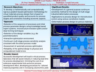
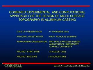
COMBINED EXPERIMENTAL AND COMPUTATIONAL APPROACH FOR THE DESIGN OF MOLD SURFACE TOPOGRAPHY IN ALUMINUM CASTING. DATE OF PRESENTATION : 11 NOVEMBER 2003 PRINCIPAL INVESTIGATOR : PROF. NICHOLAS ZABARAS PERFORMING ORGANIZATION : MATERIALS PROCESS DESIGN

E N D
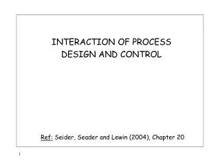
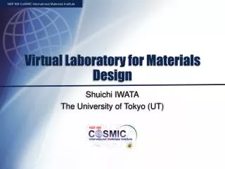
COMBINED EXPERIMENTAL AND COMPUTATIONAL APPROACH FOR THE DESIGN OF MOLD SURFACE TOPOGRAPHY IN ALUMINUM CASTING DATE OF PRESENTATION : 11 NOVEMBER 2003 PRINCIPAL INVESTIGATOR : PROF. NICHOLAS ZABARAS PERFORMING ORGANIZATION : MATERIALS PROCESS DESIGN AND CONTROL LABORATORY, CORNELL UNIVERSITY PROJECT START DATE : 31 AUGUST 2002 PROJECT END DATE : 31 AUGUST 2005 Materials Process Design and Control Laboratory
Industrial Partners Alcoa Technical Center, Alcoa Center, PA Ingot and Solidification Platform (Dr. Alvaro Giron, Coordinator) • Provide experimental data • Validate important results obtained through simulations • Perform pilot experiments to demonstrate and validate • key modifications and technologies developed Materials Process Design and Control Laboratory
Project Background and Objectives • Aluminum industry relies on direct chill casting for aluminum ingots • Presence of defects in ingots • Surface defects removed by scalping – post casting process • Defects caused by non – uniform heat extraction, improper contact • at metal/mold interface, inverse segregation, meniscus freezing etc. • Post scalping operations remove significant amount of material to • eliminate defects • Substantial energy and cost requirements for defect removal • processes, re-melting, etc. Materials Process Design and Control Laboratory
Project Background and Objectives Surface defects in casting (a) (c) (a) Sub-surface liquation and crack formation on top surface of a cast (b) Ripple formation (c) Non-uniform front and undesirable growth with non-uniform thickness (b) Materials Process Design and Control Laboratory
Liquation TCG Sweats Folds Cold shuts Blebs Project Background and Objectives Classification of direct cast surface defects in direct chill cast ingots Surface tears Cracks Pre-solidification cracks Post-solidification cracks Bleed bands Subsurface segregation and non-uniform microstructure CAST SURFACE DEFECTS Surface irregularities Duplex micro. Ripples/Laps Surface porosity Cavities Gas porosity Blisters Oxide patches Materials Process Design and Control Laboratory
Project Background and Objectives Materials Process Design and Control Laboratory Materials Process Design and Control Laboratory
Project Background and Objectives Materials Process Design and Control Laboratory
Project Background and Objectives • Some mold surface • topographies used in • Alcoa • Profound effects on the • morphology of final cast • surfaces Materials Process Design and Control Laboratory
Project Background and Objectives Materials Process Design and Control Laboratory
Project Background and Objectives • Identify mechanisms that impact shell surface morphology and microstructure • Investigate the effect of these mechanisms individually in metals and alloys • Develop inverse techniques to design mold surface topographies for desired • cast surface morphologies • Propose design solutions that reduce post-casting operations Materials Process Design and Control Laboratory
Milestones Materials Process Design and Control Laboratory
Milestones Materials Process Design and Control Laboratory
Milestones Materials Process Design and Control Laboratory
Technical Decision Points Mold topography: • Use of distorted or grooved molds to arrest or suppress gap nucleation • Modify heat transfer/solidification rate, thermal contact resistance, wettability • by using grooved molds • Effect of varying mold topographies on solidification of pure Aluminum and • Aluminum alloys Uneven growth Plain mold plate Even growth Mold plate with grooves Materials Process Design and Control Laboratory
Technical Decision Points Contact resistance: • At the very early stages of casting, the solid shell is in contact with the mold and the • thermal resistance between the shell and the mold is defined by the contact conditions • Uneven contact pressure generates an uneven thermal stress development and • accelerates distortion or warping of the shell. • Before gap nucleation, the thermal resistance • is determined by pressure • After gap nucleation, the thermal resistance • is determined by the size of the gap Example: Aluminum-Ceramic Contact Heat transfer retarded due to gap formation Materials Process Design and Control Laboratory
Air gap related events and resulting defects Shell formation Cast Surface defects Shell distortion & mold movement • Bleed bands • Blobs • Liquation • Presolidification cracks Air gap formation Re-melting of shell Flow of interdendritic residual melt Reduction in heat transfer Crack initiation Ref: Anyalebechi, P. N., ALCOA (2000) Technical Decision Points Materials Process Design and Control Laboratory
Technical Decision Points Meniscus freezing: • Occurs during mold filling • Repeated contact of melt with the mold during • solidification • Leads to ripple formation (periodic surface defects) Meniscus formation without wave mechanism (a) (b) Ripples on a cast surface: (a) linear, (b) horizontal defects Meniscus freezing using wave mechanism (Ref: Stemple, D.K. and Flemings M. C., 1982) Materials Process Design and Control Laboratory
Meniscus freezing related events and resulting defects Meniscus freezing Cast Surface defects Partial growth of the shell over the meniscus • Cold shuts/Laps • Ripples • Bleed bands • Inverse segregation Liquid metal restrained from contact with mold wall by the solidified meniscus Overflow of meniscus Reheating of shell Mechanical bending of the solid tip Ref: Anyalebechi, P. N., ALCOA (2000) Technical Decision Points Materials Process Design and Control Laboratory
Technical Decision Points Alloying elements: • Affect distortion characteristics and contact between the shell and the mold • Could lead to defects because of macro-segregation (e.g. inverse segregates, • A and V segregates) (a) Macro-segregation patterns in a steel ingots (b) Close view of a freckle in a Nickel based super -alloy blade (Ref: Beckermann C., 2000) (a) (b) Materials Process Design and Control Laboratory Materials Process Design and Control Laboratory
Technical Decision Points Mold materials: • May improve or retard heat transfer between metal and mold • Affect gap nucleation time (very important during the initial stages of solidification) Fluid flow: • Improve heat transfer rate due to convection • Changes in solid-liquid front morphology because of convection • Affects macro-segregation and inverse segregation in alloys Degree of superheat: • Increases thermal load • Improves wettability and metal-mold contact • Increases heat flux Finer microstructure Smooth solid-shell interface Materials Process Design and Control Laboratory
Technical Accomplishments • Development of a volume-averaged based stabilized finite element simulator • for modeling melt flow in alloy solidification processes • Development of a simulator for modeling deformation and thermal stresses • in solidifying bodies including air-gap formation and growth • Parametric studies of solidification of aluminum on sinusoidal surfaces • characterized by amplitude A and wavelength λ. Parametric studies of the • effects of mold topography, melt flow, superheating, mold material, etc. • Investigation of melt flow `periodic structure formation’ as a possible • mechanism affecting the solidifying shell growth. Materials Process Design and Control Laboratory
Deformation Problem Definition • Heat transfer in the mold, solid shell and melt • Heat transfer causes deformation (thermal stress development) • Mold/shell deformation & contact/frictional conditions affect heat transfer Materials Process Design and Control Laboratory
Gap nucleation time: effects of wavelength • At the very early stages of aluminum solidification, contact pressure between the mold and the solid shell will drop at the trough due to thermal stress development. When this contact pressure reaches zero, gap nucleation is assumed to take place. • For rigid mold (with an topography • amplitude =1 µm, wavelength=1-5 mm), under liquid pressure 8000 Pa, the gap nucleation time • is in the order of seconds. • Physical conditions: • Liquid pressure P=8000 Pa • Thermal resistance at mold-shell interface R=10-5 m2oCsec J-1 Materials Process Design and Control Laboratory
Gap nucleation time: effects of mold conductivity • Mold conductivity affects gap nucleation time • The higher the conductivity, the quicker the gaps nucleate from the mold surface In this calculations, the deformation of the mold is neglected to illustrate the effects of mold conductivity. Physical conditions: Liquid pressure P=10000 Pa Mold thickness h=0.5 mm Thermal resistance at mold-shell interface R=10-5 m2oCsec J-1 Wavelength=2 mm Materials Process Design and Control Laboratory
Gap nucleation time: effects of mold material (deformable mold) • When the wavelength is relatively small, the evolution of the contact pressure at the trough is mainly affected by the conductivity of the mold, i.e. the deformation of the mold does not play a crucial role. Physical Conditions: Liquid pressure P=10000 Pa Mold thickness h=0.5 mm Thermal resistance at mold-shell interface R=10-5 m2oCsec J-1 Wavelength=10 mm, (20 mm, 30 mm in the next two slides) Materials Process Design and Control Laboratory
Gap nucleation time: effects of mold material (deformable mold) • When the wavelength increases, the Ptr-t line is about to show a turn-around pattern when pressure reaches zero. This is defined as the `critical wavelength’ as in the analytical studies of L. Hector (2001) From this figure, we can say that the critical wavelength is slightly above 20 mm. In Hector’s analytical study, the critical wavelength is 16.60 mm, for iron mold and 14.03 mm for lead mold under the same conditions. Materials Process Design and Control Laboratory
Gap nucleation time: effects of mold material (deformable mold) • When the wavelength is greater than the critical value, the Ptr-t curve shows a turn- around pattern before the contact pressure reaches zero. • The pressure will not • decrease to 0 for an iron or • lead mold, so a large • wavelength is preferred • In practice, it is difficult to • obtain such a smooth mold • topography with amplitude 1 • µm and wavelength 30 mm. Materials Process Design and Control Laboratory
Shell thickness at gap nucleation time (rigid mold) • The shell thickness at gap nucleation time plays an important role in deformation. • The thicker the shell, the higher its ability to prevent distortion or warping. • From our calculations, using high • melt pressure is the preferred option • to achieve larger shell thickness at • gap nucleation time. Materials Process Design and Control Laboratory
Coupling fluid flow, heat transfer and deformation • Oscillation of contact will cause oscillation of temperature and stress Materials Process Design and Control Laboratory
Stress development • The sinusoidal mold topography would decrease the stress at the trough, but increase the stress at the crest due to small gaps formed at the trough (not visible in this figure). Materials Process Design and Control Laboratory
Conclusions from calculation before gap nucleation • Shell thickness at gap nucleation time is proportional to wavelength and liquid pressure. So a high pressure or a large wavelength is preferred. • Before gap nucleation, the solid shell is in perfect contact with the mold. Heat flux would be larger, microstructure will be finer, and the growth pattern stable. So if possible, we should avoid gap nucleation. • In practice, the liquid pressure is normally not very high, and the cast surface cannot be very smooth. So gap nucleation is unavoidable and happens very quickly, especially when the amplitude is large or the wavelength is small. In our calculation, amplitude is selected to be 1μm. • Since gap nucleation happens very soon, the growth pattern is mainly determined after gap nucleation. Materials Process Design and Control Laboratory
Shell growth after gap nucleation • After gap nucleation, the heat flux between the mold and the shell is determined by • the contact condition 1mm 5mm Solid-liquid interface Alcoa chill cast results Vcast = 25mm/s Conclusion: A smaller wavelength is preferred, because the growth pattern will become stable much faster. Materials Process Design and Control Laboratory
Solidification on uneven surfaces • Solidification of Aluminum on uneven surfaces characterized by • a sinusoid of amplitude A and wavelength λ q = 0 ux = uy = 0 • Presence of a lateral heat transfer component between the • crests and troughs • Assumption of a rigid mold in contact with metal (not modeled here) • Convective heat transfer coefficient assumed constant ux = uy = 0 ux = uy = 0 • Amplitude A and wavelength λvaried for parametric analysis • of heat transfer, fluid flow and phase change Ti = Tm + ΔT q = 0 Degree of superheat, ΔT = 50 oC Ambient temperature, T0 = 25 oC q = 0 Initial temperature, Ti = 710 oC Convection heat transfer Coefficient, hconv = 0.05 kW m-2 oC-1 λ y 2A x ux = uy = 0 q = h (T – T0) Materials Process Design and Control Laboratory
Isotherms and liquid volume fraction contours at different stages of solidification A = 0.5 mm λ = 10 mm (a) (b) (c) (d) (a), (b) liquid volume fraction contours (c), (d) isotherms Materials Process Design and Control Laboratory
Isotherms and liquid volume fraction contours at different stages of solidification A = 0.5 mm λ = 20 mm (a) (b) (c) (d) (a), (b) liquid volume fraction contours (c), (d) isotherms Materials Process Design and Control Laboratory
Isotherms and liquid volume fraction contours at different stages of solidification A = 1 mm λ = 10 mm (b) (a) (c) (d) (a), (b) liquid volume fraction contours (c), (d) isotherms Materials Process Design and Control Laboratory
Streamlines as a function of time A = 0.5 mm λ = 10mm A = 0.5 mm λ = 20mm Materials Process Design and Control Laboratory
Streamlines at different stages of solidification A = 1 mm λ = 10 mm (e) (f) Materials Process Design and Control Laboratory
Solidification on uneven surfaces Times for start of phase change for different A-λ combinations Streamfunction values for different A-λ combinations Materials Process Design and Control Laboratory
Solidification on uneven surfaces • Starting time for phase change greatly affected by change in thermal conditions • Fluid flow in the vicinity of sinusoid significantly affected, a well defined melt flow • periodicity • Gap formation substantially affects heat transfer from the mold to the shell • Effect of heat transfer on the solid-liquid front morphology substantial (more than the • corresponding effect of fluid flow) • At constant amplitude, shorter wavelength preferable for greater heat transfer • At constant wavelength, higher amplitude preferable for greater heat transfer • Front grows faster but is more distorted for higher amplitudes, when wavelength is kept • constant • Formation of smaller flow cells near the sinusoidal surface, which later dissolve into a • larger cell Materials Process Design and Control Laboratory
Macro-segregation in alloys • Macro-segregation major cause of defects in alloys • Current research focus on modeling inverse segregation, • driven by shrinkage and solutal convection in alloys • Surface segregation and exudation in alloys being modeled • simultaneously • Continuum single domain model based on volume averaged • transport equations used for this purpose • Analysis is being extended to model inverse segregation on • uneven surfaces • Effect of inverse segregation on microstructure to be modeled Steady state macro-segregation patterns for directional solidification Materials Process Design and Control Laboratory
Problems Encountered • Modeling transport phenomena on the scale of surface roughness • Simulation of gaps and their transient growth after gap nucleation • Incorporation of microstructure evolution into the current analysis • Effect of mold topography and surface parameters on microstructure • Deformation of alloys and the effect of macrosegregation on stress • development Materials Process Design and Control Laboratory
Energy Metrics • Data collected from Aluminum Association’s Aluminum Statistical Review 2000 • and Aluminum Association’s LCI report for North American Aluminum industry • Net shipments of sheet and plate (made from rectangular ingots) = 10800 • million lb • With average semi-fabricating recovery of 60%, 18000 million lb of rectangular • ingot cast in 2000 • Approximately 5% of each rectangular ingot lost in ingot scalping process • Success of research and subsequent implementations assumed to give a • reduction of 50% reduction in ingot scalping Materials Process Design and Control Laboratory
Energy Metrics • Amount of scalper chips would decrease from 900 million lb to 450 million lb. • Reverbatory furnaces commonly used for melting aluminum • - 20 – 45% efficiency and energy consumption = 0.75 – 1.7 kWh/kg • - total energy requirement = 153 – 347 million kWh per year • The potential manufacturing energy savings from successful implementation • of these technologies are estimated around 0.5 - 1.2 TRILLION BTU/year. Materials Process Design and Control Laboratory
Ongoing research and future plans • Modeling macrosegregation and inverse segregation in alloys solidifying on • uneven surfaces and their effects on the microstructure • Modeling meniscus freezing and related defects, and coupling it with current • analysis on an uneven surface • Sensitivity analysis for aluminum solidifying on an uneven surface incorporating • all the mechanisms discussed herein • Inverse techniques for design of mold surface topography for desired characteristics • in the cast surface • Development of a mathematical model to study deformation of solidifying alloys • in the presence of a mushy zone • Characterizing the effects of surface parameters and surface roughness on • microstructure of a cast alloy Materials Process Design and Control Laboratory
Ongoing Research and Future plans • Shell growth kinetics • uneven growth • distortion Metal/mold interaction Air gap formation (non uniform contact and shell remelting) Meniscus instability Varying stresses in solid Lap marks, ripples, cold shuts Interfacial heat transfer Inverse segregation Microstructure evolution Surface parameters and mold topography in transport processes Macrosegregation Materials Process Design and Control Laboratory
Commercialization Plan • The technology developed within this project is to be made available through • journals and presentations • Alcoa will incorporate this knowledge to facilitate commercialization • At the present fiscal year, commercialization is not on the agenda Materials Process Design and Control Laboratory
Awards/Recognition • “A stabilized finite element method for flow in porous media and solidification systems”, • Proceedings of the Seventh U.S. National Congress on Computational Mechanics, • presented at the Symposium on ‘Stabilized and Multi-length scale methods’, Seventh • U.S. National Congress on Computational Mechanics, Albuquerque, New Mexico, • July 27-31, 2003 • “A stabilized volume-averaging finite element method for flow in porous media and • binary alloy solidification processes”, International journal of Numerical Methods in • Engineering, in press. • “Solidification of Aluminum alloys on uneven surfaces”, submitted in the symposium on CFD Modeling and Simulation of Engineering Processes, 2004 TMS annual meeting and exhibition, Charlotte, North Carolina, March 14-18, 2004 • “Effect of mold surface topography on the freezing front morphology during aluminum • casting”, submitted in the symposium on Solidification of Aluminum alloys, 2004 TMS • meeting and exhibition, Charlotte, North Carolina, March 14-18, 2004 • Number of students supported = 2 • Deep Samanta • Lijian Tan Materials Process Design and Control Laboratory