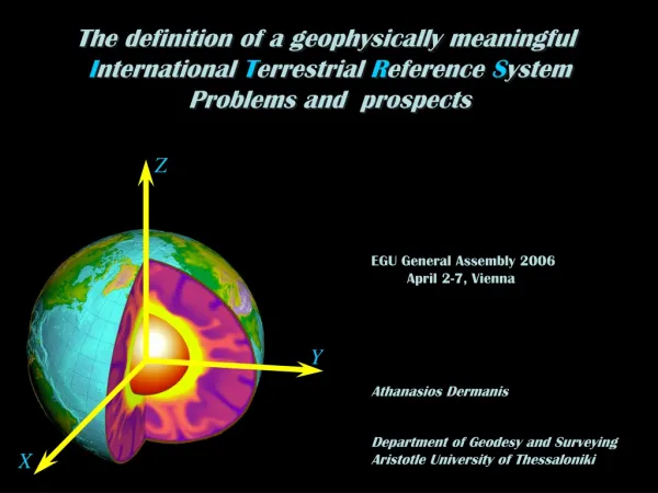
The definition of a geophysically meaningful I nternational T errestrial R eference S ystem
The definition of a geophysically meaningful I nternational T errestrial R eference S ystem Problems and prospects. Z. EGU General Assembly 2006 April 2-7, Vienna. Y. Athanasios Dermanis. Department of Geodesy and Surveying Aristotle University of Thessaloniki. X.

The definition of a geophysically meaningful I nternational T errestrial R eference S ystem
E N D
Presentation Transcript
The definition of a geophysically meaningful International Terrestrial Reference System Problems and prospects Z EGU General Assembly 2006 April 2-7, Vienna Y Athanasios Dermanis Department of Geodesy and Surveying Aristotle University of Thessaloniki X
Objective (theory): Express deformation of the earth by the temporal variation of earth point coordinates with respect to an optimally selected International Terrestrial Reference System (ITRS) Objective (practice): Provide a realization of the ITRS by an International Terrestrial Reference Frame (ITRF), consisting of the coordinate functions xi(t), yi(t), zi(t) of points Pi in a global geodetic network
Objective (theory): Express deformation of the earth by the temporal variation of earth point coordinates with respect to an optimally selected International Terrestrial Reference System (ITRS) Objective (practice): Provide a realization of the ITRS by an International Terrestrial Reference Frame (ITRF), consisting of the coordinate functions xi(t), yi(t), zi(t) of points Pi in a global geodetic network Available data: Coordinates xi(tk), yi(tk), zi(tk) of points in subnetworks at discrete epochs tk (e.g. daily or weekly solutions) with respect to a different reference systems for each subnetwork
Objective (theory): Express deformation of the earth by the temporal variation of earth point coordinates with respect to an optimally selected International Terrestrial Reference System (ITRS) Objective (practice): Provide a realization of the ITRS by an International Terrestrial Reference Frame (ITRF), consisting of the coordinate functions xi(t), yi(t), zi(t) of points Pi in a global geodetic network Available data: Coordinates xi(tk), yi(tk), zi(tk) of points in subnetworks at discrete epochs tk (e.g. daily or weekly solutions) with respect to a different reference systems for each subnetwork Problem (theory): Introduce a principle leading to an optimal choice of the reference frame Problem (practice): Combine the known shapes of the overlapping subnetworks into the shape of a global network expressed by coordinates with respect to the already defined optimal reference system
dm x The optimal choice of reference system General characteristic: Apparent motion (coordinate variation) of mass points should be minimal For the whole earth Tisserand principle: Vanishing relative angular momentum Minimal relative kinetic energy
dm x xi The optimal choice of reference system General characteristic: Apparent motion (coordinate variation) of mass points should be minimal For the whole earth For a network of discrete points i Tisserand principle: Discrete Tisserand principle: Vanishing relative angular momentum Vanishing relative angular momentum Minimal relative kinetic energy Minimal relative kinetic energy
dm x xi The optimal choice of reference system General characteristic: Apparent motion (coordinate variation) of mass points should be minimal For the whole earth For a network of discrete points i Tisserand principle: Discrete Tisserand principle: Define orientation of the reference system. For the position: Preservation of the center of mass: Trivial choice: mi =1
The “linear” model It is not possible to have all shape related parameters which are coordinate invariants as linear functions of time! No ! Is there a linear model for deformation?
The “linear” model It is not possible to have all shape related parameters which are coordinate invariants as linear functions of time! No ! Is there a linear model for deformation? A planar counterexample: The 5 shape defining sides are linear functions of time: s1 s2 s3 si = ait + bi , i = 1,2,3,4,5 s4 s5
The “linear” model It is not possible to have all shape related parameters which are coordinate invariants as linear functions of time! No ! Is there a linear model for deformation? A planar counterexample: The 5 shape defining sides are linear functions of time: s1 s2 s3 si = ait + bi , i = 1,2,3,4,5 d s4 d = nonlinear in t s5 The 2nd diagonal of the quadrilateral is not a linear function of time!
The “linear” model x(t) = x0t + vx , y(t) = y0t + vy, z(t) = z0t + vz, What is the meaning of linear model for coordinate functions? Linear coordinates in one reference system Non-linear coordinates in another CHANGE OF REFERENCE SYSTEM x(t) = x0t + v x(t) = R(t) x0t + R(t) v + c(t) x0(t) t + v x´(t) = R(t) x(t) + c(t)
The “linear” model x(t) = x0t + vx , y(t) = y0t + vy, z(t) = z0t + vz, What is the meaning of linear model for coordinate functions? x(t) x´(t) = R(t) x(t) + c(t) areboth Tisserand R(t) = R = const. c(t) = c = const.
The “linear” model x(t) = x0 + tvx , y(t) = y0 + tvy, z(t) = z0 + tvz, What is the meaning of linear model for coordinate functions? x(t) x´(t) = R(t) x(t) + c(t) areboth Tisserand R(t) = R = const. c(t) = c = const. Ad hoc definition of “linear deformation” model: Coordinates in one (and hence all) Tisserand system are linear functions of time Note: Tisserand reference system here means: Orientation by Tisserand principle (zero relative angular momentum) Position by center of mass preservation principle
The Tisserand reference system conditions for the linear model Vanishing relative angular momentum: Constant (zero) center of mass coordinates: Tisserand conditions: Tisserand conditions: Usual choice:
The Tisserand reference system conditions for the linear model Used at the stage of data analysis as additional constraints + Usual inner constraints for the definition of reference frame at epoch t0 = Selection of a single Tisserand frame out of a set of dynamically equivalent ones Vanishing relative angular momentum: Constant (zero) center of mass coordinates: Tisserand conditions: Tisserand conditions: Usual choice:
~ x(t) = R(t)x(t) dm Accessing a geophysically meaningful reference system ~ x(t) (discrete) Tisserand x(t) (earth) Tisserand ~ To accessR(t) transforming hR(Earth) to hR(Earth)=0we need an approximation of hR(Earth)
~ x(t) = R(t)x(t) dm Accessing a geophysically meaningful reference system ~ x(t) (discrete) Tisserand x(t) (earth) Tisserand ~ To accessR(t) transforming hR(Earth) to hR(Earth)=0we need an approximation of hR(Earth) To accessR(t) transforming hR(Earth) to hR(Earth)=0we need an approximation of hR(Earth) Plates Interior 0 Earth E = P1 + … + PK + … + PL + P0 Subnetwork on plate PK Network D = D1+ … + DK + … +DL UseDKto accesshPK(t) !
Estimation of the rigid motion of a plate x=RKx Transformation such that original velocities Z Z Subnetwork DK Y Y Plate PK X X
K Estimation of the rigid motion of a plate x=RKx Transformation such that original velocities Z Z determine rotation RK toreference system best fitted to DK RK Subnetwork DK transformed velocities Y Y Plate PK X X
K Estimation of the rigid motion of a plate x=RKx Transformation such that original velocities Z Z determine rotation RK toreference system best fitted to DK RK Subnetwork DK transformed velocities Y assume rigid motion of plate PK due only to rotation RK Y Plate PK X velocities due to rigid plate rotation only X
K Estimation of the rigid motion of a plate x=RKx Transformation such that original velocities Z Z determine rotation RK toreference system best fitted to DK RK Subnetwork DK transformed velocities Y assume rigid motion of plate PK due only to rotation RK Y Plate PK X velocities due to rigid plate rotation only X compute relative angular momentum of plate PK due only to rotation RK
~ x= Rx Previously estimated Final transformation to an approximate Earth-Tisserand reference system
~ x= Rx Previously estimated Final transformation to an approximate Earth-Tisserand reference system Approximate (numerically sufficient) solution for the linear model: xi(t) = x0i + tvi
~ x= Rx Previously estimated Final transformation to an approximate Earth-Tisserand reference system Approximate (numerically sufficient) solution for the linear model: xi(t) = x0i + tvi 1 Subnetwork DK relative angular momentum inertia matrix
~ x= Rx Previously estimated Final transformation to an approximate Earth-Tisserand reference system Approximate (numerically sufficient) solution for the linear model: xi(t) = x0i + tvi 1 Subnetwork DK relative angular momentum inertia matrix 2 Plate PK rotation vector inertia matrix
~ x= Rx Previously estimated Final transformation to an approximate Earth-Tisserand reference system Approximate (numerically sufficient) solution for the linear model: xi(t) = x0i + tvi 1 3 Subnetwork DK total rotation vector relative angular momentum inertia matrix 2 Plate PK rotation vector inertia matrix
~ x= Rx Previously estimated Final transformation to an approximate Earth-Tisserand reference system Approximate (numerically sufficient) solution for the linear model: xi(t) = x0i + tvi 1 3 Subnetwork DK total rotation vector relative angular momentum inertia matrix 4 new linear model 2 Plate PK rotation vector inertia matrix only velocities updated !
Thanks for your attention ! A copy of this presentation can be downloaded from: http://der.topo.auth.gr
the Intercommission Committee on Theory (ICCT) of the International Association of Geodesy (IAG) invites you to the VI Hotine-Marussi Symposium of Theoretical and Computational Geodesy: Challenge and Role of Modern Geodesy May 29 - June 2, 2006, Wuhan, China hope to see you there !