Download
1 / 22
220 likes | 340 Vues
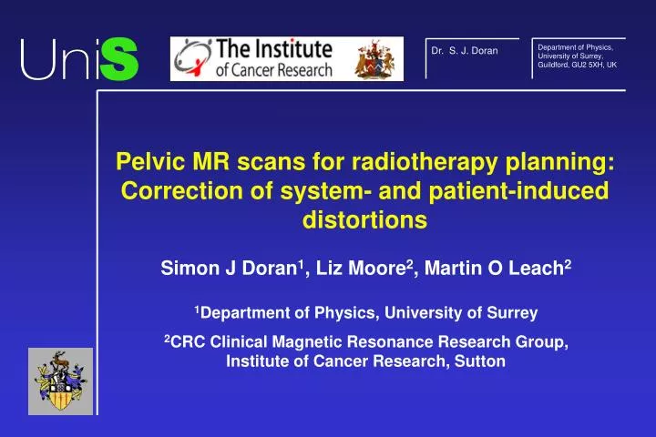
S. Department of Physics, University of Surrey, Guildford, GU2 5XH, UK. Dr. S. J. Doran. Pelvic MR scans for radiotherapy planning: Correction of system- and patient-induced distortions. Simon J Doran 1 , Liz Moore 2 , Martin O Leach 2 1 Department of Physics, University of Surrey

E N D
S Department of Physics, University of Surrey, Guildford, GU2 5XH, UK Dr. S. J. Doran Pelvic MR scans for radiotherapy planning: Correction of system- and patient-induced distortions Simon J Doran1, Liz Moore2, Martin O Leach2 1Department of Physics, University of Surrey 2CRC Clinical Magnetic Resonance Research Group, Institute of Cancer Research, Sutton
Acknowledgements • David Finnigan • Steve Tanner • Odysseas Benekos • David Dearnaley • Steve Breen • Young Lee • Geoff Charles-Edwards
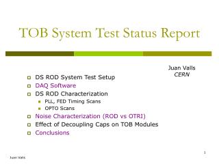
Summary of Talk • The problem of distortion • Strategy for solving the problem • Chang and Fitzpatrick algorithm (B0-induced distortion) • Linear test object (gradient distortion) • Current limitations of the method • Patient trials and validations of system in progress
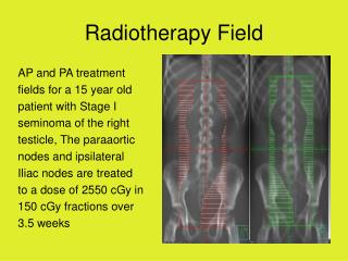
Radiotherapy Thermotherapy Stereotactic surgery Correlation of MR with other modalities (image fusion) Potential Applications The Problem • For many applications, MR provides better diagnostic information than other imaging modalities. • However, MR images are not geometrically accurate they cannot be used as a basis for planning procedures • Can we correct all the sources of distortion in an MR image?
Mathematical statement of the problem I(r) =Itrue(r-Dr) whereDr =Dr(r) Dr is a 3-D vector, whose magnitude and direction both depend on position.
Sources of distortion: (1) B0-induced • Source of the problem is incorrect precession frequency in the absence of gradients due to poor shim or susceptibility variations in sample chemical shift variations in sample Data source: C.D. Gregory, BMRL
+15 DBz / arb. units % error in Bz 0 -10 Isocentre 250 250 250 250 Isocentre x / mm x / mm z / cm z / mm 0 0 Sources of distortion: (2) gradient-induced • Source of the problem is incorrect change in precession frequency when gradients are applied. Data courtesy R Bowtell, University of Nottingham
Strategy for solving problem • FLASH 3-D sequence – susceptibility and CS lead to distortion only in read direction (unlike EPI) • Acquire data twice – forward and reverse read gradients. • Correct for B0-induced distortions with Chang and Fitzpatrick algorithm. IEEE Trans. Med. Imag. 11(3), 319-329 (1992). • Use linearity test phantom to establish gradient distortions. • Remove gradient distortions using interpolation to correct position and Jacobian to correct intensity.
fwd rev Chang and Fitzpatrick algorithm • We have two data sets, F and R, which we treat row by row. • For a given row, F(xF) dxF = R(xR) dxR . • Calculate points xR corresponding to xF.Then xtrue = (xF + xR) / 2 . corr - fwd corr corr - rev
The “linearity test phantom” (1) • Why do we need it? Can’t we get theoretical results? • Manufacturers very protective of this sort of data • Need to guarantee “chain of evidence” for e.g., radiotherapy • Is the gradient system subtly malfunctioning? • robust, light, fixed geometry • mechanical interlocks give reproducible position in magnet • 3 orthogonal arrays of water-filled tubes • square lattice of spots in each orthogonal imaging plane.
Coronal Transverse Sagittal The “linearity test phantom” (2)
X-ray CT vs. MRI of linearity test phantom Slice offset 0 mm Slice offset -185 mm
System distortion mapping algorithm: Step 1 • Acquire 3-D datasets with forward and reverse read gradients. • Match spots between the CT and MRI datasets for transverse plane and correct for distortion in read direction to give single MRI dataset. • Calculate displacement of each point Dx, Dy • Reformat the data to give sagittal and coronal projections.(A different matrix of spots appears in each plane.) • Repeat the matching process: Coronal Dx, Dz • Sagittal Dy, Dz
10 x-distortion / mm -10 100 200 y / mm x / mm -100 -200 System distortion mapping algorithm: Step 2 • Interpolate and smooth data to provide complete 3-D matrices of gradient distortion values. Example: x-distortion on transverse plane at slice offset 117.5 mm reconstructed from transverse images
^ I(x, y, z) = Idist(x-Dx, y-Dy, z-Dz) . J(x, y, z) System distortion mapping algorithm: Step 3 • Taking the known distortion data, correct the images: • Sample the 3-D data Idist at appropriately interpolated points. • Correct for intensity distortions using the Jacobian. B0 corrected B0&Grad - B0 corrected B0&Grad
Problems remaining with the technique • We currently have incomplete mapping datafrom the current phantom. Modifications to design of linearity test phantom Further data processing using full 3-D dataset • Problem of slice warp:
Patient study and validation • Protocol is being tested on patients diagnosed with prostate cancer and undergoing CT planning for conformal, external beam radiotherapy. • 4 patients have undergone both CT and MRI to date. • Protocol (total time ~20 mins.) • 3-D FLASH, TR / TE 18.8 ms / 5 ms • FOV 480 x 360 x 420 mm3 (256 x 192 x 84 pixels) 5mm “slices” • FOV 480 x 360 x 160 mm3 (256 x 192 x 80 pixels) 2mm “slices” • Each sequence repeated twice (forward and reverse read gradient) • Image registration and comparison with CT now underway.
CT MRI Once we have the corrected MR images ... • Validation via 3-D image registration of MRI with CT using champfer-matching • Assess impact of MR-based radiotherapy plans • Ultimate goal: to give us the ability to use MRI alone for radiotherapy planning MRI dataset fed into treatment planning software
MR vs. CT Dose-volume histogram for planning treatment volume - patient data • Data for 4 patients analysed so far • Early indications show excellent agreement between treatments calculated with X-ray CT and those calculated on the basis of MR images.
The slice the scanner tells us we are selecting The slice we actually get ! System distortion mapping algorithm: Step 3 • Problem: The slices are not themselves flat — slice warp! E.g., for a transverse plane, we have Dx and Dy, but we don’t know exactly which z- position they correspond to
System distortion mapping algorithm: Step 3 • Solution: Use the complete set of data acquired • Consider the x-distortion • We have two estimates of Dx, acquired from matching spots on transverse and coronal reformats of the original dataset. • For Dxtra(x, y, z), z is not known correctly because of slice warp. • For Dxcor(x, y, z), y is not known correctly. • But we can estimate unknowns from the data we have ... • Dz can be estimated from the coronal or transverse reformats and so used to correct Dxtra and similarly Dy can be estimated to correct Dxcor.