Principles of Mass Spectrometry: Analytical Methods and History of Isotope Hydrology
420 likes | 498 Vues
Explore the history and principles of mass spectrometry in isotope hydrology, from Goldstein's observations to modern analytical methods. Learn about ion separation and ion sources in the analysis of stable isotopes.

Principles of Mass Spectrometry: Analytical Methods and History of Isotope Hydrology
E N D
Presentation Transcript
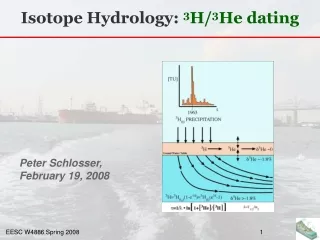
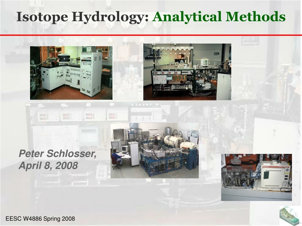
Isotope Hydrology: Analytical Methods Peter Schlosser, April 8, 2008
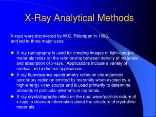
History of mass spectrometry • 1886: Eugen Goldstein observed "rays" that travelled through the channels of a perforated cathode in a low pressure gas discharge and moved toward the anode, in the opposite direction to the negatively charged cathode rays. Goldstein called these positively charged anode rays "Kanalstrahlen" or canal rays. • Wilhelm Wien found that strong electric or magnetic fields deflected the canal rays and, in 1899, constructed a device with parallel electric and magnetic fields that separated the positive rays according to their charge-to-mass ratio (Q/m). Wien found that the charge-to-mass ratio depended on the nature of the gas in the discharge tube. • EnglishscientistJ.J. Thomson later improved on the work of Wilhelm Wien by reducing the pressure to create a mass spectrograph. • The processes that more directly gave rise to the modern version of the mass spectrometer were devised by Arthur Jeffrey Dempster and F.W. Aston in 1918 and 1919 respectively. http://en.wikipedia.org/wiki/Mass_spectrometry#History
Principles of MS http://www.chemguide.co.uk/analysis/masspec/howitworks.html
Principles of MS FL: Lorentz force q: Charge of ion B: Magnetic field v: velocity of ion
Principles of MS • Ek: Kinetic energy • EE: Electric energy • V: Electric potential • U: Potential difference: Voltage • n: electric charge state of ion • e: elementary charge • v: velocity of ion
Principles of MS • r: Ion trajectory radius • q: Electrical charge of ion • B: Magnetic field • m: Mass of ion • Ek: Kinetic energy • EE: Electric energy • V: Electric potential • U: Potential difference: Voltage • n: electric charge state of ion • e: elementary charge • v: velocity of ion
Principles of MS constant
3H/3He measurements LDEO VG 5400 Noble Gas Mass Spectrometer dedicated to tritium measurements
3H/3He measurements http://www.ldeo.columbia.edu/~etg/ms_ms/Ludin_et_al_MS_Paper.html
3H/3He measurements http://www.ldeo.columbia.edu/~etg/ms_ms/Ludin_et_al_MS_Paper.html
3H/3He measurements http://www.ldeo.columbia.edu/~etg/ms_ms/Ludin_et_al_MS_Paper.html
3H/3He measurements http://www.ldeo.columbia.edu/~etg/ms_ms/Ludin_et_al_MS_Paper.html
3H/3He measurements http://www.ldeo.columbia.edu/~etg/ms_ms/Ludin_et_al_MS_Paper.html
3H/3He measurements http://www.ldeo.columbia.edu/~etg/ms_ms/Ludin_et_al_MS_Paper.html
3H/3He measurements http://www.ldeo.columbia.edu/~etg/ms_ms/Ludin_et_al_MS_Paper.html
3H/3He measurements http://www.ldeo.columbia.edu/~etg/ms_ms/Ludin_et_al_MS_Paper.html
3H/3He measurements http://www.ldeo.columbia.edu/~etg/ms_ms/Ludin_et_al_MS_Paper.html
3H/3He measurements http://images.google.com/imgres?imgurl=http://www.sisweb.com/art/galileo/44-1.gif&imgrefurl=http://www.sisweb.com/ms/galileo/galileo1.htm&h=133&w=200&sz=3&hl=en&start=5&sig2=tFYakdJcGvaT2nr8gic3Ow&um=1&tbnid=jB8HFihGBOamqM:&tbnh=69&tbnw=104&ei=euP6R9bOLIioeYTF0ZwB&prev=/images%3Fq%3Dchanneltron%26um%3D1%26hl%3Den%26rls%3Dcom.microsoft:en-us:IE-SearchBox%26rlz%3D1I7ADBF%26sa%3DN http://www.ldeo.columbia.edu/~etg/ms_ms/Ludin_et_al_MS_Paper.html
3H/3He measurements http://www.ldeo.columbia.edu/~etg/ms_ms/Ludin_et_al_MS_Paper.html
3H/3He measurements The ion separation power of a mass spectrometer is described by the resolution, which is defined as:R = m / Δ m,where m is the ion mass and Δ m is the difference in mass between two resolvable peaks in a mass spectrum. E.g., a mass spectrometer with a resolution of 1000 can resolve an ion with a m/e of 100.0 from an ion with an m/e of 100.1. http://www.ldeo.columbia.edu/~etg/ms_ms/Ludin_et_al_MS_Paper.html
3H/3He measurements http://www.ldeo.columbia.edu/~etg/ms_ms/Ludin_et_al_MS_Paper.html
3H/3He measurements http://www.ldeo.columbia.edu/~etg/ms_ms/Ludin_et_al_MS_Paper.html
3H/3He measurements http://www.ldeo.columbia.edu/~etg/ms_ms/Ludin_et_al_MS_Paper.html
AMS: Tandem systems https://www.llnl.gov/str/Knezovich.html
AMS: Tandem systems http://www.physics.purdue.edu/primelab/introduction/ams.html#tandem
The ion source produces a beam of ions (atoms that carry an electrical charge) from a few milligrams of solid material. The element is first chemically extracted from the sample (for example, a rock, rain water, a meteorite) then it is loaded into a copper holder and inserted into the ion source through a vacuum lock. Atoms are sputtered from the sample by cesium ions which are produced on a hot spherical ionizer and focused to a small spot on the sample. Negative ions produced on the surface of the sample are extracted from the ion source and sent down the evacuated beam line towards the first magnet. At this point the beam is about 10 microamps which corresponds to 1013 ions per second (mostly the stable isotopes). AMS: Ion Source http://www.physics.purdue.edu/primelab/introduction/ams.html#tandem
AMS: Injector Magnet The injector magnet bends the negative ion beam by 90° to select the mass of interest, a radioisotope of the element inserted in the sample holder, and reject the much-more-intense neighboring stable isotopes. Several vacuum pumps remove all the air from the beamline so the beam particles have a free path. There are still lots of molecules and isobars (isotopes of neighboring elements having the same mass) that must be removed by more magnets after the accelerator. http://www.physics.purdue.edu/primelab/introduction/ams.html#tandem
The tandem accelerator consists of two accelerating gaps with a large positive voltage in the middle. Think of it as a bridge that spans the inside of a large pressure vessel containing CO2 and N2 insulating gas at a pressure of over 10 atmospheres. The bridge holds two long vacuum tubes with many glass (electrically insulating) sections. The center of the accelerator, called the terminal, is charged to a voltage of up to 10 million volts by two rotating chains. The negative ions traveling down the beam tube are attracted (accelerated) towards the positive terminal. At the terminal they pass through an electron stripper, either a gas or a very thin carbon foil, and emerge as positive ions. These are repelled from the positive terminal, accelerating again to ground potential at the far end. The name tandem accelerator comes from this dual acceleration concept. The final velocity is a few percent of the speed of light or about 50 million miles per hour. AMS: Tandem Accelerator http://www.physics.purdue.edu/primelab/introduction/ams.html#tandem
AMS: Tandem Accelerator http://www.ams.ethz.ch/about/facilities/tandy/molecular
AMS: Magnets The analyzing and switching magnetsselect the mass of the radionuclide of interest, further reducing the intensity of neighboring stable isotopes. In addition, they eliminate molecules completely by selecting only the highly charged ions that are produced in the terminal stripper. (Highly charged molecules are unstable since they are missing the electrons that bind the atoms together). Isotope ratios are measured by alternately selecting the stable and radioisotopes with the injector and analyzing magnets. http://www.physics.purdue.edu/primelab/introduction/ams.html#tandem
AMS: Electrostatic Analyzer The electrostatic analyzer is a pair of metal plates at high voltage that deflects the beam to the left by 20 degrees. This selects particles based on their energy and thus removes the ions that happen to receive the wrong energy from the accelerator. The gas ionization detector counts ions one at a time as they come down the beamline. The ions are slowed down and come to rest in propane gas. As they stop, electrons are knocked off the gas atoms. These electrons are collected on metal plates, amplified, and read into the computer. For each atom, the computer determines the rate of energy loss and from that deduces the nuclear charge (element atomic number) to distinguish interfering isobars. http://www.physics.purdue.edu/primelab/introduction/ams.html#tandem
AMS: Ion Detection Bethe – Bloch formula http://www.physics.purdue.edu/primelab/introduction/ams.html#tandem
AMS: Ion Detection http://images.google.com/imgres?imgurl=http://www.science.uottawa.ca/~eih/ch1/Image13.gif&imgrefurl=http://www.science.uottawa.ca/~eih/ch1/ch1.htm&h=494&w=626&sz=13&hl=en&start=4&sig2=Z5DBM0EtIFLLDnucLsSgAQ&tbnid=vUvsSPpvfJvW9M:&tbnh=107&tbnw=136&ei=hGL7R_vxIJDQed6-mbcB&prev=/images%3Fq%3Dmass%2Bspectrometry%2Bnier%2Bsource%26gbv%3D2%26hl%3Den
AMS: Ion Detection http://www.ipp.phys.ethz.ch/research/experiments/tandem/Diss_Michal.pdf
AMS: Ion Detection http://www.ipp.phys.ethz.ch/research/experiments/tandem/Diss_Michal.pdf
AMS: Tandem systems http://www.physics.arizona.edu/ams/education/ams_principle.htm
AMS: Tandem systems https://publicaffairs.llnl.gov/news/news_releases/2006/images/cams359x274.jpg
AMS: new developments http://www.ipp.phys.ethz.ch/research/experiments/tandem/tandy/Tandy_home.html
Gas Chromatography http://en.wikipedia.org/wiki/Image:Gas_chromatograph.png
Common inlet types are: S/SL (Split/Splitless) injector; a sample is introduced into a heated small chamber via a syringe through a septum - the heat facilitates volatilization of the sample and sample matrix. The carrier gas then either sweeps the entirety (splitless mode) or a portion (split mode) of the sample into the column. In split mode, a part of the sample/carrier gas mixture in the injection chamber is exhausted through the split vent. On-column inlet; the sample is here introduced in its entirety without heat. PTV injector; Temperature-programmed sample introduction was first described by Vogt in 1979. Originally Vogt developed the technique as a method for the introduction of large sample volumes (up to 250 µL) in capillary GC. Vogt introduced the sample into the liner at a controlled injection rate. The temperature of the liner was chosen slightly below the boiling point of the solvent. The low-boiling solvent was continuously evaporated and vented through the split line. Based on this technique, Poy developed the Programmed Temperature Vaporising injector; PTV. By introducing the sample at a low initial liner temperature many of the disadvantages of the classic hot injection techniques could be circumvented. Gas source inlet or gas switching valve; gaseous samples in collection bottles are connected to what is most commonly a six-port switching valve. The carrier gas flow is not interrupted while a sample can be expanded into a previously evacuated sample loop. Upon switching, the contents of the sample loop are inserted into the carrier gas stream. P/T (Purge-and-Trap) system; An inert gas is bubbled through an aqueous sample causing insoluble volatile chemicals to be purged from the matrix. The volatiles are 'trapped' on an absorbent column (known as a trap or concentrator) at ambient temperature. The trap is then heated and the volatiles are directed into the carrier gas stream. Samples requiring preconcentration or purification can be introduced via such a system, usually hooked up to the S/SL port. SPME (solid phase microextraction) offers a convenient, low-cost alternative to P/T systems with the versatility of a syringe and simple use of the S/SL port. GC: Inlet Types http://en.wikipedia.org/wiki/Gas_chromatography