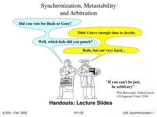
Metastability (What?)
Metastability (What?). Tom Chaney, tchaney@blendics.com Dave Zar, dzar@blendics.com. TexPoint fonts used in EMF. Read the TexPoint manual before you delete this box.: . Metastability Is. a fundamental property of all bi-stable circuits (flip-flops and arbiters)

Metastability (What?)
E N D
Presentation Transcript
Metastability (What?) Tom Chaney, tchaney@blendics.com Dave Zar, dzar@blendics.com TexPoint fonts used in EMF. Read the TexPoint manual before you delete this box.:
Metastability Is • a fundamental property of all bi-stable circuits (flip-flops and arbiters) • the cause of ambiguous output voltages and unpredictable behavior • the reason for setup & hold-time constraints on flip-flops • When observed they eliminate metastability • When violated may lead to circuit malfunction • Satisfying constraints perfectly between multiple independent clock domains is not possible
Results for a D-Latch C’ V1 D Q’ C • Latch output before final inverter (clock is also shown). • Rightmost two traces bracket unbounded metastable point
Prototypical Master-Slave DFF SLAVE MASTER C’ C V2 V1 D Q C’ C
Results for a Master-Slave • Clock is shown in yellow. • Other traces are obtained by varying the data-clock separation and observing the output of the FF before the output inverter.
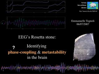
Real plots! Times and voltages far from normal experience And History Dependent! – must collect data slowly 6 6 7 7 Photos of ECL circuits taken about 45 years ago. VCLK 1 0 pulse (2.5 0 0.063028851134n 0.5n 0.5n 100n 200n) Vdata 2 0 pulse (0 2.5 0n 0.5n 0.5n 100n 200n) These measured waveforms represent an input timing resolution of about 100 asec. psec fsec asec zepto sec
Clock B Clock A A Synchronizer Failure Clock Domain A Synchro- nizer Clock Domain B Clock B Synchronizer Output Voltage Recovering from Metastability Domain B Switching Thresholds Synchronizer fails and future behavior of Domain B unknown Domain B Clock Edge
Probability of Synchronizer Failure(Noise Free Case First) The probability of failure is the probability that the output of the synchronizer is unresolved at a clock edge: V1 Resolved Gtv = slope = 0.67VDD Dv Vm = ½VDD Not Resolved 0.33VDD Distribution of DataEvents Resolved Dt Data Setup and Hold Region t 0TC Clock TC
Circuit Model Analysis Cm V1 Use small signal analysis V1 Cn V1 gmV2 Cn Cm V2 2V0 V0 V2 Cn Cn t = 0 t = t’ gmV1 Cm For V0 small Result
MTBF for Synchronizers The probability of failure is the probability that the synchronizer output is unresolved at the next clock edge: V1 Resolved 0.67VDD With a uniform distribution of data events in a clock period Dv 2Ve Not Resolved From the definitions of Gtv and the circuit model Resolved 0.33VDD Distribution of DataEvents we see that Data Dt Setup and Hold Region t 0TC 0TC Clock TC
MTBF Based on Aperture Time The probability of failure is the probability that the synchronizer output is unresolved at the next clock edge: V1 Resolved 0.67VDD Dv 2Ve Not Resolved Resolved 0.33VDD Distribution of DataEvents Data ta Setup and Hold Region t 0tcy 0 Clock tcy
Synchronizer Failure Trend • System failures due to synchronizer failures have been rare, but will be more likely in future • Many more synchronizers in use (Moore’s Law) • Systems with 100s of synchronizers, perhaps 1000s soon • Systems with synchronizers in million-fold production • Small changes in Vt cause large changes in • Growing parameter variability in nano-scale circuits • In an IBM 90 nm process Vt varies for 0.4 to 0.58 volts • Transistor aging increases vulnerability • An ASU model shows Vtincreasing by 5% over 5 years • Clock domains may not have uncorrelated clocks
Is There A Perfect Solution? • Theoretical results show metastability is a fundamental problem of all bi-stable circuits • Failures caused by metastability are always a possibility • between two independently clocked domains • between a clock domain and outside world • One solution uses asynchronous circuits, but real-time applications may still be problematic • Another solution uses synchronizer circuits and designers must hope failures are rare
Completion Detection • It is not possible to bound the amount of time needed for a synchronizer to settle. • It is, however, possible to detect when the synchronizer has settled! • This is only useful if the downstream logic can use this asynchronous completion signal
What Could Go Wrong? • It’s easy to get a synchronizer design wrong • The three most common pitfalls are: • using a non-restoring (or slowly restoring) flip-flop • needs to be small • not isolating the flip-flop feedback loop • Using two flip-flops in parallel • The last pitfall is doing everything “right” but not understanding that influences MTBF!
Correlated Clocks Osc. PLL A PLL B Core A Sync. Core B Although Cores A and B may be clocked at different rates, these rates are based on the same oscillator and are thus correlated. This relationship between the synchronizer’s clock and data inputs can be very malicious.
Correlated Clocks & Noise • The effects of correlated clocks and the effects of noise can be approached similarly. • As we will see, circuit noise may be treated as one case of correlated clocks.
Region of Vulnerability: Dt Gtv = 0.67VDD Dv = DtGtv Vm = ½VDD TC 0.33VDD Distribution of DataEvents Dt Data t Setup and Hold Region 0TC 0TC Clock
Malicious Data Events DTDGtv 0.67VDD DtGtv Vm = ½VDD 0.33VDD Distribution of Data Events TD Dt Data Setup and Hold Region t 0TC Clock
Malicious Data EventsEven More Malicious DTDGtv 0.67VDD DtGtv Vm = ½VDD 0.33VDD Distribution of Data Events TD Dt Data Setup and Hold Region t 0TC Clock
Effects of Thermal Noise 0.67VDD * = Vm = ½VDD Thermal Noise 0.33VDD Input Distribution of Data Events Resultant Distribution t 0TC Bottom Line: Thermal noise pushes as many events into the window of vulnerability as is pushes out.
Upper Bound on Punresolved What happens when Td is very small? 0.67VDD * = Vm = ½VDD 0.33VDD Thermal Noise Input Distribution of Data Events Resultant Distribution t 0TC Bottom Line: Thermal noise establishes an upper bound on Punresolvedand a lower bound on MTBF
Calculating MTBF Always a stochastic calculation Assume clock and data unrelated If related, thermal noise gives lower bound E.g. clock and data from same source or clockless Thermal noise voltage standard deviation: This lower bound is 2 to 3 orders of magnitude smaller than when clock and data are unrelated
MTBF Affects System Behavior • Assume: • Desired probability of system failure = 1 : 2,000,000 • System lifetime is 30 years (~ 10 9 sec) • System has 50 processors with 10 synchronizers each • Then: • Need MTBF of 30 billion years (3·1010) per synchronizer • But: • Corner cases can further reduce needed MTBF • If clock and data are related, must use lower bound set by thermal noise: MTBFn • Unwise to use conventional MTBF formula without understanding its limitations
Master-Slave DFF MTBF Examples 90 nm process =39.83 ps, Gtv=0.375 V/ns, fd = 133 MHz 125 ps setup time assumed MTBF ranges from 1 day to 9.7·1037 years MTBFn ranges from 11.5 minutes to 2.1·1035years
Parameter Variations in Master-SlaveProcess-Voltage-Temperature 200 MHz 200 MHz Clock; 90 nm process, 125 ps setup time MTBF ranges from 5.07·104 years to 4.16·10110 years MTBFn ranges from 112 years to 1.09·10109years
Latch Versus Master-Slave FFMTBF @200 MHz 200 MHz Clock; 90 nm process, 125 ps setup time