Download
1 / 59
1.01k likes | 2.35k Vues
WELDING INSPECTION AND QUALITY CONTROL. Upon completion of this module you will be able to: Identify the different inspection methods used in non destructive testing. The uses and the limitations of the different inspection methods. Perform Visual Inspection. Introduction.

E N D
WELDING INSPECTION AND QUALITY CONTROL Upon completion of this module you will be able to: • Identify the different inspection methods used in non destructive testing. • The uses and the limitations of the different inspection methods. • Perform Visual Inspection.
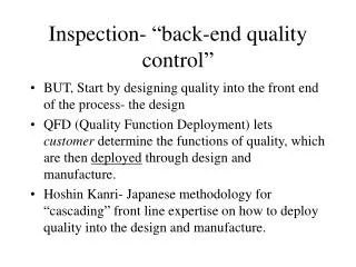
Introduction. • Inspection, Testing and qualification are growing part of QUALITY CONTROL in manufacturing and maintenance. Quality Control has become very important because of competition and liability. To compete in what has become a global marketplace, companies must produce the best products possible. The cost of inspection and testing of products can save greater expenses later on when the consumer becomes involved. Money that does not have to be spent defending the company can be used for research and development of new products. The WELDER is the person who begins quality control by being satisfied only with Quality Welding.
The welder starts the inspection in the process of welding, making immediate adjustment in response to what is being observed in the weld pool. This may require changing the amperage, the travel speed, the arc length or any of the factors that affects quality of the weld bead. Finally, the welder gives the completed weld a final Visual Inspection to look for any defects that could not be seen while welding.
Common methods used in NDE • Visual Inspection (VT) • Magnetic Particle Inspection (MT) • Liquid (Dye) Penetrant Inspection (PT) • X-Ray inspection (RT) • Ultrasonic testing (UT) • Air or water pressure testing (LT)
VISUAL INSPECTION – VISUAL TEST (VT) • What is Visual Inspection? • NDT process – non destructive testing is the original term used to identify a method of inspection that does not destroy a product usefulness. Current terms include nondestructive inspection (NDI) or nondestructive evaluation or examination (NDE) • Examination with the eye – therefore you are only able to DETECT SURFACE DISCONTINUITIES. • Most important and most extensively used NDE/NDI/NDT method (before any NDT or DT be applied.) II. Advantages A. Usually inexpensive - the majority of expense will be in the inspector’s wage. B. Equipment is small and inexpensive – there’s a lot of equipment to aid in visual inspection, but all small and inexpensive.
C. No powered required – this makes VT the most portable NDT process. D. Can avoid defects and costly repairs – by able to make intermittent inspection II. DISADVANTAGES • Requires training and experience –the inspector should be familiar with all the welding process. • Must have a good eyes – the AWS requires 20-40 natural or corrected distance acuity for a certified welding inspector. • May not detect internal defects – limited to surface discontinuities only, but it might give indication of substance indication. Then can be supplemented by some other NDT method. • No permanent records – the inspector must maintain a written log, supplemented by pictures, and tape recorded report. • Subject to human error – must spend adequate time to prevent errors.
IV. Five steps of Visual Inspection. • Inspection practice – establish a definite procedure to insure adequate and consistent coverage. • Inspection prior to welding • Inspection during welding • Inspection after welding • Marking and making repairs V. Equipment required. • Flashlight – used to remove shadows when an extension lamp can’t be used. • Magnifying glass – low power can be used with caution, if allowed by customer or code. • Protective lenses – pocket viewer with proper shade lens to watch the welding taking place. • Weld gage – are hand held measuring devices used to assist during welding and for final inspection.
E. Hammer and chisel – to remove spatter or slag from weld prior to inspection. F. Temperature Indicating Devices – some method must be used to determine the preheating, interpass and postheating temperatures. Pyrometer and tempelstick or crayons are commonly used. G. Magnet – a magnet can be used to help determine a material type.
Visual Inspection (VT) • Fillet gauges measure • The “Legs”of the weld • Convexity • (weld rounded outward) • Concavity • (weld rounded inward) • Flatness
Measuring Steel Rule Magnifying Glass Fillet Weld Gauge Palm Weld Gauge Micro Caliper Vernier Caliper
VI. Inspection Before Welding • Drawing – drawing are complete and accurate? • Position of welds – does the position called for correspond to the procedure or specification? In vertical is direction of travel correct? • Welding symbols – if they are used are they complete and accurate? • Welding procedure – is the procedure complete and accurate according to the code or specification?
E. Material • Did purchasing obtain the correct material such as base metal type and size. The correct electrode type size and the correct shielding gas type and grade. • Materials should be checked for defects. Base metal should be checked rust, mill, scale, laminations or delaminations. • Is the material preparation correct and according to procedure, such as angles and condition after preparation. F. Assembly • Inspect for proper fit up, as this will prevent discontinuities from occuring. • Jigs and fixtures will assure proper alignment. Make sure they are clean and free spatter and not damaged. • The tack welds are only short welds, but the quality must be the same as all other welds. The tack welds must be made with the same electrodes that are used for the rest of the welds.
4. Pre heat will be used to slow the cooling rate and prevent distortion. The pre heat could be used prior to tacking and / or prior to welding. G. Equipment • Inspect the equipment for any damaged such as damaged cables, damaged ground clamps, or electrode holders. Inspect the arc voltage and amperage meters making sure they are with in range. Welder Inspect before welding - Root Face - Root Gap - Bevel Angle - Joint and Fit up
VII. Inspection DURING welding. Electrodes – inspect for usage of proper electrodes, types, size and storage. Low hydrogen type must be stored in a stabilizing oven. Root pass – the first layer or root pass is the most important and is particularly susceptible to cracking. Thicker material will crack and will require more pre heat. Subsequent passes – inspection of successive layers is sometimes carried out with the assistance of workmanship standard. Check for contour or undercut as these are good places for slag to be trapped. Check for proper cleaning between passes as this can prevent slag entrapment.
D. Crater formation – make sure crater are filled as this are areas where crack are easily formed. E. Weld size and sequence – are the weld size according to the print and is the layer and sequence according to the procedure? The use of various gages will determine this. VIII. Inspection After welding • The applicable code or standard – it will list acceptance standards They will generally cover the following areas; • Weld size – use gages to check conformance to prints • Contour and finish – is the contour convex or concave, and what was called for in print? Is finish smooth and free from surface irregularities. • Cracks – the code or standard will state if any is acceptable and what size.
4. Overlap – it is an indication of lack of fusion 5. Undercut – if allowed how much? 6. Spatter – what is excessive? IX. Making repairs A. When marking areas to be repaired the marking should be positive and clear. It should be a method that is understood by all involved, should be permanent enough to be evident after the repair has been made and inspected, and the marking must not damaged the part.
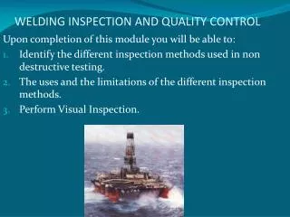
Non Destructive Testing – Dye Penetrant Test OBJECTIVE: Upon completion of this module you will be able to: 1. Understand that both Inspection and Testing are necessary for Quality Welding. 2. Identify the different inspection methods used in Non Destructive Testing and Destructive Testing 3. Describe the uses, the process and the limitations of the different non destructive inspection methods. 4. Perform Dye Penetrant Testing.
TESTING • Testing becomes necessary for several reasons. If new welding procedures are employed, the manufacturer might be interested in finding out if the welding process is producing quality welds. For example, a product welded by Shielded Metal Arc Welding may be produced more cost-effectively by a Gas Metal Arc Welding process, but will the quality be the same? The manufacturer may be interested in finding out if both the gas metal arc welding process and the filler metals are compatible with the steel used as the base metal. If the steel does not match up with the filler metal, no welding will make any difference.
There might also be the question of whether the welders have enough skill at some other welding process to make welds as sound as those made by shielded metal arc welding. No manufacturer wants to risk the company’s reputation with welds that fails to hold up. The least serious outcome might be a product that fails; the worst could be injury or death. Testing companies provide an invaluable service when it is necessary to have welding examination outside the manufacturer’s plant. Testing companies keep records and furnish the results of weld testing to insurance companies, government agencies and other interested parties. Testing companies provide an important service because, by uncovering problems in welding, they help manufacturers produce safe and durable goods and structures that consumers can live with.
TWO METHODS OF TESTING • 1. NON DESTRUCTIVE TESTING - leavesthe weldment intact, at least until the results uncover major defects in the welding. Consequently, nondestructive testing is often preferred when testing is necessary. • 2. DESTRUCTIVE TESTING - results in the destruction of weldment. This is a costly undertaking because of the time and money involved, not to mention the destruction of a weldment that might have to be re-welded. • 1. NON-DESTRUCTIVE TESTING METHODS • There are FOUR common methods of Non Destructive Testing: • Magnetic Particle test • Dye penetrant test • Ultrasonic test • Radiographic test
Dye Penetrant Test (DPT) and Fluorescent Penetrant Test (FPT) – can locate only cracks and porosity that have formed on the surface of the weld. With the dye penetrant test a highly penetrative liquid is applied to a weld that has been thoroughly cleaned. Upon drying, a developer is applied to the weld. Under normal lighting, any defects are outlined, usually in red, where the dye has been absorbed. • With the fluorescent penetrant test, the weldment is submerged in a fluorescent dye. It is removed from the dye and placed under a black light, where any defects in the weld appear greenish yellow. • Defects Detected Defects open to surface only – Cracks, slag inclusion, porosity and undercuts.
Liquid (Dye) Penetrant Inspection (PT) • Liquid penetrant inspection uses colored or fluorescent dye to check for surface flaws. • PT will not show sub-surface flaws. • PT can be used on both metallic and non metallic surfaces such as ceramic, glass, plastic, and metal. • PT dose not require the part to be Magnetized.
Advantages • a. Detects very small, tight surface and subsurface imperfections • b. Simple application and easy to interpret • c. Inexpensive • d. Use in magnetic and non magnetic materials such as ceramic, plastic • Disadvantages • a. Time consuming on various steps of the process • b. Normally no permanent record • EQUIPMENTS FOR PENETRANT TEST • Solvent Cleaner • Penetrant • Developer • Process Principle – 6 steps • Surface preparation • Penetrant application • Excess penetrant removal • Developer application • Inspection / evaluation • Post cleaning
DYE PENETRANTS • Process Principle – 6 steps 1. Surface preparation – remove oil, grease, spatter 1.1. Apply Solvent Cleaner to the area to be inspected 1.2. Use clean rags to remove excess cleaner solvent 2. Apply Penetrant and wait for 15-20 minutes dwelling time 3. Remove excess penetrant using clean rags 4. Apply Developer and wait 5 - 10 minutes dwelling time 5. Inspect and evaluate the red color formation 6. Post cleaning
Red Dots will appear if Defect is present. Very Red Color the defect is deep and not very red the defect is shallow. DETECTION
II. Application: • Ferrous and non ferrous materials • Plastic and glass – ceramics-insulators-anything that is nonporous III. Advantages: • Low cost • Ease in application and interpretation – easy to apply and interpret result, discontinuities readily visible and portable. • Less training time for applicator – easy process to learn. IV. Limitations: • Detects discontinuities that is open to surface only • Can not be used on porous or absorbent materials V. Safety a. Ventilation – check for toxic fumes from testing materials. Check for volatility -explosive or fire flash points b. Fire safety – the test material maybe non flammable but the propellant used with spray cans maybe extremely flammable.
OBJECTIVE:Upon completion of the module, you will be able to;1. Describe Magnetic Particle Testing and its limitations.2. Perform Magnetic Test • Magnetic Particle Test (MT) – (commonly referred to as Magnaflux testing)The magnetic particle test begins when Direct Current (DC) electric charges is passed between two poles. The forces line up until there is a break in these magnetic lines of force. • Magnetic particles are applied to the weld in the form of powder. Nothing unusual results when the welding is sound, but when the welding might be defective, a break is created in the lines of force. The magnetic particles become attracted to the defect, which develops north and south poles at the edge of the defect, outlining the defect.
Equipment: 1. Iron Particle, wet or dry or flourescent 2. Special power source 3. Ultraviolet light for the flourescent type • DEFECTS DETECTED: 1. Surface and near surface discontinuities 2. Cracks 3. Porosity 4. Slag Inclusions 5. Incomplete Fusion • Advantages 1. Detects discontinuities not visible to the naked eyes 2. Useful in checking edges prior to welding and repairs 3. No size restrictions • Disadvantages 1. Used in magnetic materials only 2. Surface roughness may distort magnetic field 3. Normally no permanent record
To enable the formation of a proper magnetic particle pattern for defect indication, the orientation of the defect and magnetic field must be taken into account. Two methods of magnetizing the weld zone. • The YOKE method which uses an electromagnet • The PRODE method in which electrode are applied to the specimen to allow current to flow in the specimen. - not applicable to high tensile steel since it can form a short circuit between specimen and electrodes causing a defect resembling an arc strikes. - effective to detecting defects not exposed but existing near the surface.
Two methods of magnetizing the weld zone. 2. The PRODE method in which electrode are applied to the specimen to allow current to flow in the specimen. The YOKE method which uses an electromagnet
MAGNETIC PARTICLE Two types of magnetic particles: • Fluorescent type • Non fluorescent type Methods of particle application: • Wet method – magnetic particles are dispersed by suspension in water or kerosene and the suspension is applied to the specimen surface. • Dry method –magnetic particle are dispersed in the surface of the specimen.
CoatingsUnfortunately, ASTM E-1444 specifies that Magnetic Particle testing shall not be performed with nonmagnetic coatings (paint, etc.) in place that exceed 0.003" (0.08mm) in thickness, or ferromagnetic coatings (electroplated nickel, etc.) that exceed 0.001" (0.03mm) in thickness.That is not very thick! So be careful on those painted surfaces.......don't forget the chance of poor bonding on those thin coatings.Current TypesASTM E-1444 recommends:Half-wave rectified AC is best for the dry particle method.For defects open to the surface use AC only.When using Wet particle method for subsurface defects, use full-wave rectified AC.
YokesFunny, but look at the difference, Standards can make on a procedure:ASTM E-1444 requires DC yokes to have a lifting force of at least 30 lbs.(small spacing) and a 50 lbs. lift for a large spacing of legs.ASTM A-275 requires DC yokes have a lifting power of at least 40 lbs at 3 to 6" spacing of legs.The ASME Boiler Code requires a DC yoke to have at least 40 lbs of lift at the maximum pole spacing. • There is a misconception in the 'field' that one can take a yoke and proceed with magnitizing an object by dragging the yoke along the object's surface. Wrong!!!
If you are dragging an AC yoke, you are in fact not magnetizing the object but rather you are doing a lovely job of DEMAGNETIZING the object. As in ASTM E-1444 above, paragraph 6.7.1.1, demagnetizing using a coil (yoke) by moving the object through........(which is what you are doing).To correctly magnetize an object, position the yoke and apply magnetizing force for 2 - 5 seconds before moving the unit to the next position.So watch which specification and procedure is being applied to your project.
Ultrasonic testing (UT) • Ultrasonic testing (UT) is a method of determining the size and location of discontinuities within a component using high frequency sound waves. • Sound waves are sent through a transducer intothe material and the shift in time require for their return or echo is plotted. • Ultrasonic waves will not travel through air therefore flaws will alter the echo pattern.
ULTRA SONIC oscilloscope
Equipments: 1.Oscilloscope – to generate and receive ultrasonic waves. 2. Cathode Ray Tube – where the traveling distance and intensity of reflected wave are measured to locate and determine the size of the defect. 3.Vibrating Transducer (Probe) 3.1. Straight Beam 3.2. Angle Beam 4.Calibration Blocks – to make time distance and built in holes and notches can be used as amplitude standards. • DEFECTS DETECTED: 1. Can locate all internal flaws located by other methods with the addition of exceptionally small flaws. • ADVANTAGES 1. Extremely sensitive 2. Use restricted only by very complex weldments 3. Can be used on all materials • DISADVANTAGES 1. Demands highly developed interpretation skill
Advantages: • Time to inspect – fast response / ability to inspect from one side. • B. Cost - $3,500.00 machine / $200.oo transducer • Portable with battery pack • Accuracy can locate small discontinuity Limitations: • Equipment • Operator • Standards • Reports and records
Radiographic Test (RT) • Radiographic Test is a NDT that can detect surface and internal discontinuities using electro magnetic radiation of short duration by means of either • 1. X-Ray • 2. Gamma Ray • It is a wave of energy that will pass through most materials and develop the negative image of what it passes through on film. Both of these methods are a danger to health 1. An X-Ray- Is electronically produced in a vacuum tube. 2. Gamma Ray-are emitted by the atomic decay. • Two Common Source of Gamma Rays. • Cobalt 60 • Iridium 192 • 3.FILM VIEWER • Pictures taken are viewed as negatives will only give flat image not in three dimensional darkened area must be used for viewing.
X-RAY VIEWER Pictures taken are viewed as negatives will only give flat image not in three dimensional darkened area must be used for viewing
Advantages: • A Radiograph ( X-Ray picture) is a permanent record of a weld used for quality inspection purposes • RT inspections can reveal flaws deep within a component • Limitations: • The necessity to have access to both sides of the part being radiographed • Unfavorable shape and orientation of some discontinuities. • Radiation Safety requirements for personal protection. • Tight Cracks, unless they are essentially normal to the radiation beam. • Shallow tight surface cracks in thick sections usually can not be detected at all, even when properly oriented. • Laminations are nearly impossible to detect because their orientation does not permit sufficient differences in the amount of radiation absorbed through the piece being examined to show the defect on film.
Air or water pressure testing (LEAK TEST) • Pressure testing or leak testing can be performed with either gasses or liquids. • Voids that allow gasses or liquids to escape from the component can be classified as gross (large) or fine leaks. • Extremely small gas leaks measured in PPM (parts per million) require a “Mass Spectrometer” to Sniff for tracer gases
APPLICATION OF A LOAD • Used to test pressure vessels • Pipe lines • The item for testing is filled with water or oil it is then pressurised using a pump • A safety valve is set 1.5 to 2 times below the working pressure.
PRESSURETEST Pressure Gauge Pump Test Specimen