
Tortoise Pin Configuration for DC and DCC Tracks
This document provides detailed instructions and assumptions for the pin configuration of the Tortoise switch machine in a model railroad setting. It specifically notes the orientation of Tortoise pin 1, which is crucial for proper functionality of the module. The configuration supports both DC and DCC setups, highlighting the use of various pins for track feeders, frogs, and LED indicators. Ensuring correct connections is essential for optimizing the operation of the track system.

Tortoise Pin Configuration for DC and DCC Tracks
E N D
Presentation Transcript
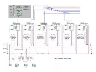
1 1 1 1 1 1 Assumes Tortoise pin 1 is toward rear (grey) of module Assumes Tortoise pin 1 is toward rear (grey) of module Assumes Tortoise pin 1 is toward rear (grey) of module Assumes Tortoise pin 1 is toward rear (grey) of module Assumes Tortoise pin 1 is toward front (red) of module Assumes Tortoise pin 1 is toward front (red) of module + - DC-1 + - + - + - DCC 12V DC-2 INNER OUTER DCC + - - + - + - + - + - + - + - + - + - + - + + - - + - + Tortoise (w/2 SPDT) TRACKS DPDT x OUTER x INNER SPDT Panel LED SPST FROG DPST FEEDER GAP x 12v OUTER Red = front rail INNER Red = front rail DCC DCC Track feeders not shown INNER OUTER DC DC