Download
1 / 35
350 likes | 360 Vues
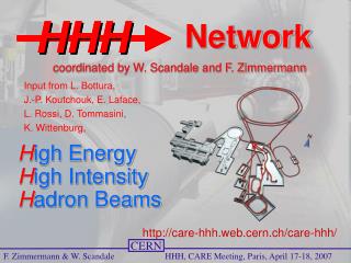
HHH Highlight Talk. H igh Energy H igh Intensity H adron Beams. Active Techniques to Mitigate the Electron-Cloud Effects in Proton Machines. http://care-hhh.web.cern.ch/care-hhh/. Frank Zimmermann, CERN. CARE’07, CERN, October 29, 2007. electron-cloud effects. pressure rise

E N D
HHH Highlight Talk High EnergyHigh Intensity Hadron Beams Active Techniques to Mitigate the Electron-Cloud Effects in Proton Machines http://care-hhh.web.cern.ch/care-hhh/ Frank Zimmermann, CERN CARE’07, CERN, October 29, 2007
electron-cloud effects • pressure rise → interlock, background, beam loss • heat load → quench of s.c. magnets • coherent tune shift → loss of Landau damping, instabilities • single and multi-bunch instabilities → beam loss, emittance growth • incoherent tune shift, nonlinear field → poor lifetime, emittance growth
electron-cloud effects seen at almost all p (& e+) accelerators INP Novosibirsk, 1965 Argonne ZGS,1965 BNL AGS, 1965 ISR, ~1972 PSR, 1988 Bevatron, 1971 AGS Booster, 1998/99 CERN SPS, 2000 KEKB, 2000 (e+)
origin of electrons • ionization of residual gas vacuum pressure • photoemission from synchrotron radiation spatial distribution of primary and reflected photons, photon reflectivity, photoemission yield • avalanche build up of secondary e- via acceleration in the beam field secondary emission yield, surface properties, conditioning,….
electron cloud in the LHC schematic of e- cloud build up in the arc beam pipe, due to photoemissionand secondary emission [F. Ruggiero]
LHC cold vacuum chamber 5-20 K beam screen inside cold bore; pumping slots
LHC strategy against electron cloud ~1997-2002 1) warm sections (20% of circumference) coated by TiZrV getter developed at CERN; low secondary emission; if cloud occurs, ionization by electrons (high cross section ~400 Mbarn) aids in pumping & pressure will even improve 2) outer wall of beam screen (at 4-20 K, inside 1.9-K cold bore) will have a sawtooth surface (30 mm over 500 mm) to reduce photon reflectivity to ~2% so that photoelectrons are only emitted from outer wall & confined by dipole field 3) pumping slots in beam screen are shielded to prevent electron impact on cold magnet bore 4) rely on surface conditioning (‘scrubbing’); commissioning strategy; as a last resort doubling or tripling bunch spacing suppresses e-cloud heat load
sawtooth structure stamped on LHC beam screen → reduced photon reflectivity → only 2% of photons reflected such that they hit top or bottom of beam screen courtesy I. Collins, 1999
“beyond LHC” – situation early 2007 • HHH LUMI’06 workshop Valencia showed e-cloud may be severe problem for new LHC injectors (PS2, SPS w PS2) • Fritz Caspers proposed solution: “e-cloud killler” based on enamel coating; established contacts in Germany • Warner Bruns (EUROTeV) wrote new e- code “Faktor2” & found novel cure: slots • CARE-HHH & CARE-ELAN supportive • wide resonance from community → ECL2 mini-workshop, 1-2 March 2007
care-hhh.web.cern.ch/CARE-HHH/ECL2 Joint CARE-HHH-APD, CARE-ELAN and EUROTEV-WP3 mini-Workshop on Electron Cloud Clearing Electron Cloud Effects and Technological Consequences Organizing committee:F. Caspers (CERN), O. Malyshev (ASTeC/Cockcroft), M. Pivi (SLAC), W. Scandale (CERN), D. Schulte (CERN), R. Wanzenberg (DESY), F. Zimmermann (CERN)
ECL2 participants • total: 35 • 16 from CERN (4 AB/ABP, 1 AB/OP, 7 AB/RF, 2 AT-VAC, 2 TS) • 3 from German enamel industry • 4 from US (BNL, Cornell, LBNL & SLAC) • 1 from KEK • 11 from European research institutes and universities (Astec, LNF, DESY, ANKA, Rostock, CELLS, U.Sannio, ESRF)
ECL2 proceedings CARE-HHH Conf CARE/ELAN doc EUROTeV report CERN-AB report
ECL2: solutions against electron cloud • TiN coating (P. Chiggiato + team, Y. Suetsugu) • Ti ZrV NEG coating (P. Chiggiato, Y. Suetsugu) • grooved surfaces (M. Pivi, M. Palmer) • conventional clearing electrodes (A. Poncet, M. Zobov) • enamel electrodes (F. Caspers) New! • slotted vacuum chamber (W. Bruns)New! • electrete inserts (F. Caspers)New! • issues: modeling, prototypes, beam experiments, suppression efficiency, impedance, vacuum issues, implications & cost
TiN coating & graphite: infrastructure for TiN coating exists at CERN; planned testing of coated liners in SPS; alternative approach: graphite layer S. Calatroni, M. Taborelli, CARE-HHH BEAM’07
PEP-II tests w. grooved & coated chambers (2007) • field-free region, 2 chambers with rectangular groove profiles, and 2 regular "flat" or smooth chambers • same inner diameter, all chambers coated with TiN! electron signal: grooved TiN-chambers « smooth TiN-chambers « regular stainless steel chamber (M. Pivi)
PS e- clearing electrode (2007) Penning gauge Shielded button pickups High-voltage feedthrough Clearing electrode T. Kroyer, E. Mahner, F. Caspers, CARE-HHH BEAM’07
PS e- cloud test bench (2007) • PS elliptical vacuum chamber with dimensions 1050 x 146 x 70 mm. • Special antechamber for clearing electrode without aperture reduction. • Material: stainless steel 316 LN T. Kroyer, E. Mahner, F. Caspers, CARE-HHH BEAM’07
2007 PS results: “islands” w. surviving EC • e- signal plotted at different times before ejection • e- build-up earlier with magnetic field; e- “islands” • for large clearing voltages (|U|> 1 kV) e- are suppressed t=-45 ms t=-20 ms last splitting t=-10 ms last splitting [1e-3] t=-1 ms adiabatic compression t=-100 ms final bunch rotation t=-2 ms prior to extraction T. Kroyer, E. Mahner, F. Caspers, CARE-HHH BEAM’07
conventional “invisible” clearing electrode at DAFNE - major impedance! - now removed from the ring F. Zimmermann, ECL2; M. Zobov, ECL2
“e- cloud killer” prototyped by Texas A&M NEG-coated 100-mm copper-foil electrode with 100-V bias voltage; insulation by 0.2 mm cover glass P. McIntyre et al, PAC2005
enamel coating – the new “e- cloud killer” (F. Caspers, F.-J. Behler, P. Hellmold, J. Wendel, ECL2)
proposed enamel solution for SPS: a strip insert High-impedance thick-film layer as clearing electrode on enamel isolator • 0.5 mm stainless steel sheet • copper coating • ~20 mm wide and ~0.1 mm thick enamel strip • on top ~15 mm highly resistive thick film layer acting as “invisible” clearing electrode • spot-welded to beam pipe Copper-coated stainless steel insert T. Kroyer, E. Mahner, F. Caspers, BEAM’07
“slotted” surface grid-like structure shields beam fields at the wall this effect may explain why ISIS never observed e-cloud standard chamber “slotted” chamber W. Bruns, ECL2
electrets • another solution proposed by Fritz Caspers at ECL2 • electret = permanently charged material, e.g. teflon subjected to e- bombardment during production • either permanent electric field is sustained over several years, or self-charging by the beam field • may allow in-situ upgrade of LHC and SPS!
possible solutions for new LHC injectors entirely new machine aperture constraints in existing magnets
summary • numerous technological concepts for suppressing e-cloud build up • enamel clearing electrodes and slotted chambers: novel promising concepts • TiN and NEG coating: still considered • additional constraints retrofitting an existing accelerator like the SPS • electrode clearing effect explored at PS • studies for PS2 & enhanced-SPS vacuum chambers progress with high momentum
appendix • open questions from ECL2 • SEY conditioning effect
open questions from ECL2 • modeling of electron cloud & e- emission - effect of beam field, magnetic field, and ions - many questions on grooves - surface parameters (e.g. Cu-st.st. difference) • enamel - SEY and PEY, impedance, stability - study suppression efficiency - can enamel coating fit into SPS chamber? • air baked Cu, radical injection, permanent el. fields • in-situ grooving? • NEG, TiN – long term stability, self-activation, heat F. Zimmermann et al, ECL2 final discussion
surface physics of secondary emission yield (SEY) • important role of surface hydrocarbons • after limited air exposure and (re-)conditioning by e- bombardment (typically 10-3C/mm2) maximum SEY of TiN decreases to 1-1.2 ; and for copper to 1.2-1.3 • two phenomena contribute to conditioning: • - particle stimulated desorption (H, CO..) and surface cleaning • - graphitization of adsorbed hydrocarbons S. Calatroni, M. Taborelli, CARE-HHH BEAM’07
secondary e- yield R. Cimino, I. Collins et al, Phys.Rev.Lett.93:014801,2004 dmax probability of elastic electron reflection may approach 1 for zero incident energy and is ~independent of d*max