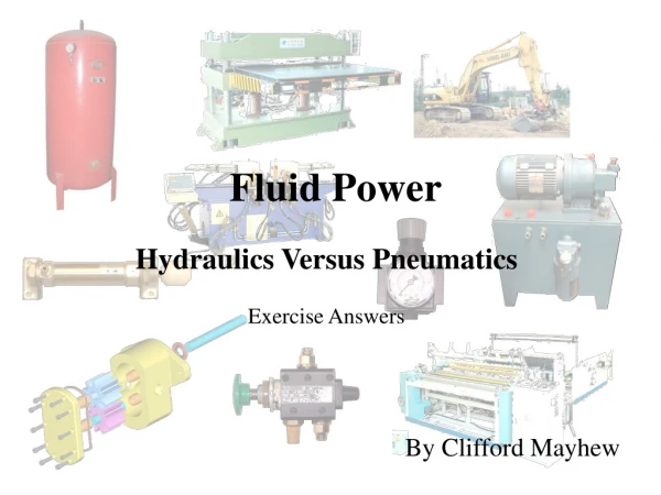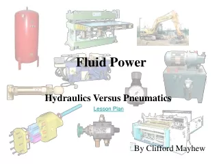
Exploring Fluid Power Technology: Advantages, Applications & Components
1.15k likes | 1.33k Vues
Discover the world of hydraulics and pneumatics, which use fluids to transmit power efficiently. Learn about the benefits, applications, and properties of hydraulic fluids. Understand the different types of fluid power systems, components, and classifications of hydraulic pumps. Find out about essential concepts like Pascal's Law, cavitation, and Reynolds number. Explore how hydraulic power is harnessed in industries such as construction, mining, and energy generation. Dive into the principles of hydraulic systems and the role of components like actuators, control valves, and accumulators.

Exploring Fluid Power Technology: Advantages, Applications & Components
E N D
Presentation Transcript
Introduction to fluid power • Fluid power is a term describing hydraulics and pneumatics technologies. • Both technologies use a fluid (liquid or gas) to transmit power from one location to another. • hydraulics, the fluid is a liquid (usually oil), • pneumatics uses a gas (usually compressed air). • Both are forms of power transmission, which is the technology of converting power to a more useable form and distributing it to where it is needed. • The common methods of power transmission are electrical, mechanical, and fluid power.
Advantages of fluid power • high horsepower-to-weight ratio — You could probably hold a 5-hp hydraulic motor in the palm of your hand, but a 5-hp electric motor might weight 40 lb or more. • safety in hazardous environments because they are inherently spark-free and can tolerate high temperatures. • force or torque can be held constant — this is unique to fluid power transmission • high torque at low speed — unlike electric motors, pneumatic and hydraulic motors can produce high torque while operating at low rotational speeds. Some fluid power motors can even maintain torque at zero speed without overheating • pressurized fluids can be transmitted over long distances and through complex machine configurations with only a small loss in power • multi-functional control — a single hydraulic pump or air compressor can provide power to many cylinders, motors, or other actuators • elimination of complicated mechanical trains of gears, chains, belts, cams, and linkages • motion can be almost instantly reversed
Application of fluid power system • Construction • Mining • Agriculture • Waste Reduction • Utility Equipment • Marine • Offshore • Energy • Metal Forming • Machine Tools • Military & Aerospace • Other Applications
Types of fluid power systems • Fluid transport system • Transport of water from reservoir using pipe lines • Transport of oil in pipe to two countries. • Fluid power system • Oil used in equipments to acquire desire movement. • Compressed air in pneumatics for crane movements
Properties of hydraulic fluids • Density • The density of a fluid is its mass per unit volume: • Liquids are essentially incompressible • Density is highly variable in gases nearly proportional to the pressure. • Note: specific volume is defined as:
Cavitation • Cloud of vapour bubble will form when liquid pressure drops below vapour pressure due to flow phenomenon • Capillarity • Liquid rises into a thin glass tube above or below its general level. • Vapour pressure • Pressure exerted by vapour which is in equilibrium with liquid
Compatibility • Ability of hydraulic fluid to be compatible with the system. • Volatility • The degree and rate at which it will vapourize under given conditions of temperature and pressure. • Corrosiveness • Tendency to promote corrosion in hydraulic system.
Application of pascals law • Hydraulic press
Laminar and Turbulent flow • Laminar • Turbulent
UNIT 2: HYDRAULIC SYSTEM COMPONENTS • Sources of Hydraulic Power • construction and working of pumps – Variable displacement pumps • Actuators: Linear hydraulic actuators • Single acting and Double acting cylinders • Fluid motors. • Control Components: • Direction control valve • Flow control valves • Electrical control -- solenoid valves. Relays, Accumulators and Intensifiers.
Basic Pump Classifications • Hydraulic pumps can be classified using three basic aspects: • Displacement • Pumping motion • Fluid delivery characteristics
Basic Pump Classifications • Displacement relates to how the output of the pump reacts to system loads • Positive-displacement pumps produce a constant output per cycle • Non-positive-displacement pumpsproduce flow variations due to internal slippage
Basic Pump Classifications • A non-positive-displacement pump has large internal clearances • Allows fluid slippage in the pump • Results in varying flow output as system load varies
Basic Pump Classifications • Non-positive-displacement pump
Basic Pump Classifications • The basic pumping motions used in hydraulic pumps are: • Rotary • Reciprocating
Basic Pump Classifications • Gear pumpsare rotary pumps Sauer-Danfoss, Ames, IA
Basic Pump Classifications • Piston pumps are reciprocating pumps Reciprocating piston movement
Basic Pump Classifications • In a rotary pump, the pumping action is produced by revolving components • In a reciprocating pump, the rotating motion of the pump input shaft is changed to reciprocating motion, which then produces the pumping action
Basic Pump Classifications • Hydraulic pumps are classified as either fixed or variable delivery • Fixed-delivery pumps have pumping chambers with a volume that cannot be changed; the output is the same during each cycle • In variable-delivery designs, chamber geometry may be changed to allow varying flow from the pump
Basic Pump Classifications • Gear pumps are fixed-delivery pumps
Basic Pump Classifications • Piston pumps may be designed as variable-delivery pumps
Basic Pump Classifications • When selecting a pump for a circuit, factors that must be considered are: • System operating pressure • Flow rate • Cycle rate • Expected length of service • Environmental conditions • Cost
Pump Design, Operation,and Application • Gear pumps are positive-displacement, fixed-delivery, rotary units • Gear pumps are produced with either external or internal gear teeth configurations
Pump Design, Operation,and Application • Gear pumps are commonly used
Pump Design, Operation,and Application • Pumping action of gear pumps results from unmeshing and meshing of the gears • As the gears unmesh in the inlet area, low pressure causes fluid to enter the pump • As the pump rotates, fluid is carried to the pump discharge area • When the gears mesh in the discharge area, fluid is forced out of the pump into the system
Pump Design, Operation,and Application • Gear pumps are available in a wide variety of sizes • Flow outputs from below 1 gpm to 150 gpm • Pressure rating range up to 3000 psi
Pump Design, Operation,and Application • The gerotor pump design is an internal-gear pump • Uses two rotating, gear-shaped elements that form sealed chambers • The chambers vary in volume as the elements rotate • Fluid comes into the chambers as they are enlarging and is forced out as they decrease in size
Pump Design, Operation,and Application • The gerotor is a common internal-gear design
Pump Design, Operation,and Application • Gerotor operation
Pump Design, Operation,and Application • Gerotor operation
Pump Design, Operation,and Application • Gerotor operation
Pump Design, Operation,and Application • Gerotor operation
Pump Design, Operation,and Application • Vane pumps are positive-displacement, fixed or variable delivery, rotary units. • Design is commonly used in industrial applications • Delivery can range up to 75 gpm • Maximum pressure of about 2000 psi
Pump Design, Operation,and Application • Vane pump consists of a slotted rotor, fitted with moveable vanes, that rotates within a cam ring in the pump housing • Rotor is off center in the ring, which creates pumping chambers that vary in volume as the pump rotates • As chamber volume increases, pressure decreases, bringing fluid into the pump • As volume decreases, fluid is forced out into the system
Pump Design, Operation,and Application • Operation of a typical vane pump
Pump Design, Operation,and Application • Parts of a typical vane pump
Pump Design, Operation,and Application • Vane pump may be pressure unbalanced or pressure balanced • Unbalanced has only one inlet and one discharge, which places a side load on the shaft • Balanced has two inlets and two discharges opposite each other, creating a pressure balance and, therefore, no load on the shaft
Pump Design, Operation,and Application • Piston pumps are positive-displacement, fixed- or variable-delivery, reciprocating units • Several variations • Many provide high volumetric efficiency (90%), high operating pressure (10,000 psi or higher), and high-speed operation
Pump Design, Operation,and Application • A basic piston pump consists of a housing that supports a pumping mechanism and a motion-converting mechanism • Pumping mechanism is a block containing cylinders fitted with pistons and valves • Motion converter changes rotary to reciprocating motion via cams, eccentric ring, swash plate, or bent-axis designs • Rotating the pump shaft causes piston movement that pumps the fluid
Pump Design, Operation,and Application • Piston pump classification is based on the relationship between the axes of the power input shaft and piston motion • Axial • Radial • Reciprocating
Pump Design, Operation,and Application • Axial piston pumps use two design variations: • Inline • Bent axis
Pump Design, Operation,and Application • Inline has the cylinder block and pistons located on the same axis as the pump input shaft • Pistons reciprocate against a swash plate • Very popular design used in many applications
Pump Design, Operation,and Application • An inline axial-piston pump
Pump Design, Operation,and Application • Bent axis has the cylinder block and pistons set at an angle to the input shaft • Geometry of the axis angle creates piston movement • Considered a more rugged pump than inline • Manufactured in high flow rates and maximum operating pressures
Pump Design, Operation,and Application • A bent-axis axial-piston pump