Download
1 / 27
270 likes | 297 Vues
Learn methods to reduce interference at mobile units & cell sites through antenna height adjustments, directional antennas, and notch patterns. Mechanical and electrical downtilting techniques explained.

E N D
Lowering the Antenna Height (a) on a high hill (b) in a valley
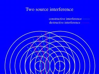
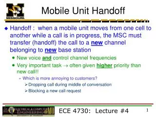
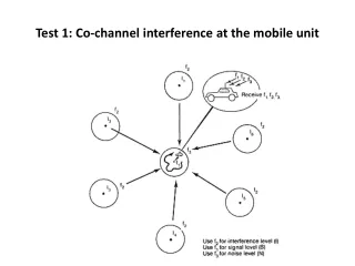
Reduction of Co-channel interference in a cellular mobile system • Increasing the separation between two co-channel cells • Using directional antennas at the base station • Lowering the antenna heights at the base station.
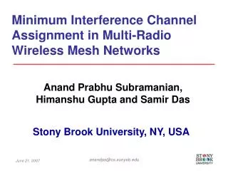
Reduction of Co-channel Interference by Means of a Notch in the Tilted Antenna Pattern A seven-cell cellular configuration
Antenna Pattern 33°,45°,65°,85° Horizontal Beamwidth Vertical Beamwidth
A typical pattern for a directional antenna of 120° beamwidth (a) Azimuthal pattern of 8-dBdirectional antenna
A typical pattern for a directional antenna of 120° beamwidth (b) Vertical pattern of 8-dB directional antenna
Antenna Tilting • In general, the vertical pattern of an antenna radiates the main energy towards the horizon • Only that part of the energy which is radiated below the horizon can be used for the coverage of the sector • Downtiltingthe antenna limits the range by reducing the field strength in the horizon
The Effect of Mechanically Downtilting Antenna on the Coverage Pattern Vertical antenna pattern of a 120° directional antenna
Mechanical Downtilting • is the down tilt angle • d1 is the length of the upper antenna-mounting arm • d2 is the length of the lower antenna-mounting arm • h is the distance between d1 and d2
Antenna Parameters Mechanical Downtilt Electrical Downtilt • HBW gets bigger • Causes gain reduction • HBW remains the same • But can’t adjust downtilt (fixed)
Umbrella-pattern Effect • Antenna in which the waves are guided downward in all directions from a central pole or tower to the ground, somewhat like the ribs of an open umbrella.