Unofficial Voith SFC Programming Guide
90 likes | 136 Vues
Detailed guide on Voith SFC programming, including PLC scan instructions, SCADA alarming setup, initialization, and housekeeping tips. Learn how to utilize SFCs efficiently and maintain alarm systems effectively.

Unofficial Voith SFC Programming Guide
E N D
Presentation Transcript
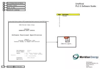
01 PLC 5 Software Guide and Manual UnofficialPLC 5 Software Guide. 02 Any Station - Generic 03 Drawn – D J Ray 04 Original is A4 – Landscape. This document forms a guide to SFC programming that is common to Voith SFC Software. GCS Support.MERIDIAN ENERGY LTD.State Highway 8,Twizel,New Zealand.
General Guide Use a single SBR to connect all discrete digital inputs to a buffer file.Use a single SBR to connect all analog inputs to a RAW (un scaled) buffer file.Use a single SBR to scale all the analog inputs using CPT instruction – use either inline scaling values or references to a scaling data file.Make all unit (generator) code the same across a station – use the DH+ address as a switch to turn on and off unit specific functions.Use SFC’s where ever possible.Use standard/generic SFC’s where ever possible.Use 1 SBR file for 1 SFC where ever possible.Use 1 Data file for 1 SFC where ever possible – however its likely more than 1 will be needed often.Describe the inputs to the SFC – Digital and Analog.
SCADA ALARMING Every PLC Scan do this – the alarm is latched into N50:10 on for reading by scada– they are latched so that a fleeting alarm is held in N50 till scada acknowledges it has read the N50: fileWhen it does ack the alarm value perform a plain COP to freshen the N50 file N50:10 = N47:10 OR N50:10 (Lgt = 40 for N47:10 to N47:49) N47: N50: N50: Logical OR Indications – both bit and integer are not latched – the N50 file is addressed directly in code.
PLC 5 Code segement to perform scada Alarm Ack Value calculation and verification – and N50 re-freshing control. If scada ack’s the alarms – by returning a Alarm Ack set point hat equals theAlarm Ack Value as computed by the PLC – the scada has ‘seen’ the currentN50 file so freshen it. If scada has not ack’ed the current alarms – keep them and add any new ones. Initalization Compute a crude value that can be used to determine if the alarming file N47 has changed.Various symetrical bit patten alarm changes will not be detected. BST EQU N51:51 N50:51 BST COP #N47:10 #N50:10 40 NXB CLR N50:51 BND NXB NEQ N51:51 N50:51 XIO R6:0/EN FAL R6:0 40 0 ALL #N50:10 #N47:10 OR #N50:10 NXB XIO R6:1/EN BST CLR F46:0 NXB FAL R6:1 40 0 ALL F46:0 F46:0 + #N50:10 BND NXB NEQ F46:0 F46:1 BST ADD N50:51 1 N50:51 NXB MOV F46:0 F46:1 BND NXB GRT N50:51 1000 MOV 1000 N50:51 BND If the alarming file has changed – INC the Alarm Ack Value – this is passed to scada.Which will return it – indicating it has seen the current state of N50 House keeping Limiting – 1,000 is a lot of alarm changes.
VOITH CAN RTD Alarming & Tripping RTD’s Each Fault bit is derived by ths sort of rung A trip is derived like this Or a high alarm like this.
A SFC – Normally 1 per SBR but often more than one are found in a SBR A typical Voith SFC consists of the following code segments – in the following order.Inputs to SFCDerivedStep TimersStep ControlStep DecoderStep Outpts Typical overview of the code sctions that make up a SFCand the order and size they take in any one ladder file. Inputs to SFC Derived Step Timers Step Control Step Decoder Step Outpts
This is a standard Voith Step Decoder and Controller.N80 for step wordsB81 for step bitsB83:0 is a buffer location used by many SFC decoders.N7:100 is a buffer location used by many SFC decoders.Each step is guaranteed to be true for at lest one scan if the rule below is used…1:- Never used the step word for state tests – always use the step bit.