Automated Room Environment Control
Automated Room Environment Control. Group 9. Andrew Battles, Edward Vettel, Seunggue Koo ECE 445 Senior Design December 4 th , 2008. The environment control system regulates the light and temperature of a room. Separates room into regions:

Automated Room Environment Control
E N D
Presentation Transcript
Automated Room Environment Control Group 9 Andrew Battles, Edward Vettel, Seunggue Koo ECE 445 Senior Design December 4th, 2008
The environment control system regulates the light and temperature of a room. Separates room into regions: Adjusts light separately by region so no area is overly/ insufficiently lit. Operates fan to circulate air, eliminate pockets of warm or cool air. Introduction
Objectives • Keep a consistent amount of light throughout a large room, accounting for outside illumination • Keep a consistent temperature throughout room, eliminating cool or warm pockets • Allow users to update and store multiple desired light/temperature settings
Features • Simple user interface, can be operated with only a mouse or touch screen • Multiple light sensors per area create more accurate data • Multiple temperature sensors placed throughout room take into account inconsistencies • Individual dimmer for each light to adjust light levels for each region independently
Benefits • Save electricity by only using the minimum amount of light needed • Eliminate “hot spots” within a room near heat producing devices or large groups of people. • Keep a room lit properly during periods of variable light, such as sunsets, sunrises, and cloudy days
Benefits (cont.) • Keep areas of the room that are far from windows as well lit as areas receiving plenty of natural light. • One-touch preset selection and real-time light dimming for convenience
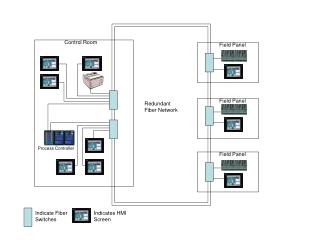
System Overview • Hardware: • HCS12, Dimmer Circuit, Relay Circuit • 10 Temperature Sensors, 3 Light Sensors, 3 Digital Potentiometers • Air Conditioner, Heater, and Fan • Power Supply • Software: • Labview User Interface • HCS12 Operation coded in C • Room Construction
Power Supply (Purchased) • BP5081A15 AC/DC Converter • Outputs 5 VDC, 12 VDC, and 24 VDC
Hardware Overview • HCS12 • Microcontroller that runs entire system • Dimmer Circuit • Controls power to lights in room • Relay Circuit • Switches power to Heater/Cooler/Fan • LM35 Precision Temperature Sensor • Detects temperature of room
Hardware Overview • TSL2550 Ambient Light Sensor • Detects level of light in room • Digital Potentiometer • Varies resistance in dimmer circuit • Power Supply • Takes A/C power from bench and converts it to 5 VDC and 12 VDC
User Interface • Simple use: can be utilized with a touch screen or a monitor and mouse. • 8 Memory slots to save desired settings • Communication over serial port
User Interface • Light goes from 0 (no power to bulb) to 252 (full power to bulb) in increments of 4 • 64 discreet light levels = 6 bits of data • Temperature goes from 50oF (10oC) to 104oF (40oC) in increments of half-degrees Celcius: • 61 discreet temperature levels = 6 bits of data
User Interface • Light, temperature, heat/cool mode, and SET bit all packaged into one 16 bit word • Bottom six bits for light level (0-63) • Next six bits for temperature level (0-59) • Bit 14 for heat/cool mode • Bit 15 = SET bit, so microcontroller knows if it will be accepting new values • Data sent out through RS-232 serial port to microcontroller
User Interface • Easy to test • Created simple monitor box off to side • Shows what values will be output, their binary counterparts, and the control word sent to the microcontroller in both binary and hex
User Interface Performance • Overall, the user interface performed flawlessly on its own • Intuitive interface, easy to use without previous exposure to it • Error-free operation • Compact data output
HCS12 Microcontroller • Brand new microcontroller for ECE 445 • Prototyping board and blank Codewarrior project developed by Bill Eisenhower
Program Code • Main program’s most basic functions: • Before looping • Set up & initialize communication with peripherals • Start up sensors (A/D conversions) • Forever loop • Read from user interface, sensors • Perform calculations • Adjust lighting, temperature devices
Communication Challenges • Each separate comm port must be properly initialized and matched to the baud rates of each peripheral device • Each device has different: • Way of communicating • Feedback method • Initialization procedure • Way of representing collected data or interpreting sent data
A Particularly Complex Case • Light sensors communicate over IIC port • One IIC port on HCS12, 10 light sensors • All light sensors have same slave address: no way to differentiate! • Solution: Multiplex the bus
Success and Failure • Using the Codewarrior development suite, we were able to successfully simulate the proper operation of our all of our code • Suite allows you to set virtual registers and variables while stepping through code line by line. Our simulation: • Waits where it is supposed to • Reads and writes to proper registers • Updates variables and performs calculations correctly
Success and Failure • Using the HCS12 Monitor of the design suite, we were able to confirm successful basic operation of the HCS12 in real time • Initialized and accessed registers properly • Initialized internal clock for communication with external devices • Output data through general I/O ports to demonstrate patterns on flashing LEDs • Repeated simple programs indefinitely
Success and Failure • We were successfully able to output values from the general I/O ports to light up LEDs • We were unable use general I/O ports as inputs • This was not a part of the final design, but would have been useful for testing • Repeated attempts disabled the HCS12, even though voltage and current input were well within acceptable limits
Success and Failure • We were unable to read the commands sent from the user interface • Convoluted nature of the SCI communication code we used was very confusing, difficult to find out where we were going wrong • We were unable to read from the light sensor/MUX array • We could not get the IIC communcation to operate properly, and were therefore unsure of any data received
Success and Failure • HCS12 kept burning out, so we avoided testing its A/D conversion until that issue was resolved. It still is not resolved, and confuses us as well as the designer of our HCS12 protoboard. • Microcontroller becomes disabled frequently and without a consistent pattern, which greatly inhibits debugging.
Dimmer Circuit Overview • Controls power to lights in room • Includes: • 120 VAC • AD5290 Digital Potentiometer • HD-40 Diac • MAC228A6 Triac
HD-40 Diac • Bidirectional Trigger Diode • Breakover voltage between 35 and 45 V
MAC228A6 Triac • Bidirectional Triode Thyristor • Peak off-state voltage of 400 V • Peak Gate current of ± 2 A.
AD5290 Digital Potentiometer • 256 Positions • Input digital, outputs analog • HCS12 sends 8-bits • Digital Potentiometer sets corresponding resistance
Dimming the Circuit: the Diac and Triac • Digital Potentiometer • Capacitor • Diac Trigger • Triac Voltage
Testing the Dimmer Circuit • Simulations
Testing the Dimmer Circuit • Varying the resistance with an analog potentiometer • Improvising for Diac
Challenges • 10K variable resistor in series with 100K • Range of brightness too small • 256 steps not necessary • AD5290 not rated for circuit voltage • Lowest measured voltage across analog potentiometer around 80 V • AD5290 rated for 30 V
Success and Failure • We were successfully able to dim the light bulbs using manual potentiometers • The AD5290 was not rated for the high AC voltage and could not be used • Using a lower voltage source failed due to high Diac breakover voltage
Sensors Overview • LM35 Precision Temperature Sensor • Accurate within 0.5 ⁰C • Outputs 10 mVDC / ⁰C • Ambient Light Sensor with SMBus Interface • Converts light intensity to digital signal
Testing the temperature sensors • Output of LM35 is 10 mV / ⁰C • Lab temperature is about 23.5 ⁰C • Output rises when sensors are heated
Relay Circuit Overview • Interfaces with HCS12 • Triggers power to heater/cooler/fan
T75S5D112 Relay Input : 3.6~5V DC coil voltage, 18mA~42mA coil current required Can control AC & DC both Control up to 14 Amps Output from HCS12 5V DC, 25mA Digital Logic Circuit: T75S5D112
A/C & Heater power control - Inputs: 0-5V input voltage from HCS12 control signal - Operation: Connect 120VAC for turning on Fan power Control Inputs: 0-5V input voltage from HCS12 control signal Operation: Connect 12VDC for turning on Diode - Safety: protect Micro controller from inverse current from the coil Control Implementation
Results Relay logic circuit works well when we tested with 5V power supply. In condition : 3.6V~5V, 20mA~ Did not function with output of HCS12: Current too low PCB can handle the current amount when A/C, Heat Lamp, Fan are on at the same time. More than fuse could take! Relay Test
Not sufficient current from HCS12 Even though we expected maximum 25mA following the data sheet, the output current from HCS12 was less than 0.001mA. The circuit did not work with HCS12 So, we decided to change the circuit design to neglect the current amount Using Forward bias of NPN Transistor . Challenges
NPN Transistor Negligible current amount from HCS12 Voltage controlled Diode Added for Safety reason Inverse current from the relay coil may cause malfunction on microcontroller. Stability Transistors and diodes can be easily damaged. New Additions
Microcontroller Recommendations • Use analog-output light sensors instead of IIC to avoid need for long chains of multiplexing operations • Use as few types of peripheral communication as possible, as debugging the communication is the largest time commitment • Avoid using HCS12 unless experienced at using microcontrollers, as it is still very new • Few examples to look at on implementation • Information on how to use it sparse/difficult to understand • HCS12 has trouble handling FOR loops over 30000 cycles: use recursive loops to go over this amount