Download
1 / 18
180 likes | 421 Vues
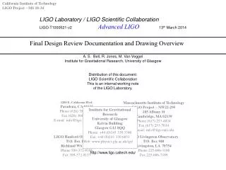
California Institute of Technology LIGO Project – MS 18-34. LIGO Laboratory / LIGO Scientific Collaboration LIGO-T1000521-v2 Advanced LIGO 13 th March 2014. Final Design Review Documentation and Drawing Overview. A. S. Bell, R. Jones, M. Van Veggel

E N D
California Institute of Technology LIGO Project – MS 18-34 LIGO Laboratory / LIGO Scientific Collaboration LIGO-T1000521-v2 Advanced LIGO 13th March 2014 Final Design Review Documentation and Drawing Overview A. S. Bell, R. Jones, M. Van Veggel Institute for Gravitational Research, University of Glasgow Distribution of this document: LIGO Scientific Collaboration This is an internal working note of the LIGO Laboratory. Institute for Gravitational Research University of Glasgow Kelvin Building Glasgow G12 8QQ Phone: +44 (0)141 330 3340 Fax: +44 (0)141 330 6833 Web: www.physics.gla.ac.uk/igr/ http://www.ligo.caltech.edu/
Final Design Review Documentation and Drawing Overview This presentation is designed to allow one to follow the documentation path down an assembly by clicking on an item. In PDF format this will not work, but one can still navigate manually to the same place Colour coding Review documentation directly linked to file Review documentation linked to another slide Referenced documentation directly linked to file Referenced documentation linked to another slide Document change log: Pre-v1 – first draft for circulation in fibre group meeting
Top-level break-down documentation T1000337 Monolithic Stage Final Design Document Design requirements docs Monolithic Assembly Docs Preparation masses Fibre pulling and welding
Design requirement docs Design requirements docs T020034 Low-frequency cut-off aLIGO T010075-00 aLIGO systems design In PDR T010075-00 was referenced, document was updated to T010075-01 in Apr 2008 change impact monolithic unknown Further update in 2012 to T010075-02 no impact on monolithic T000053-04 Universal sus subsystem design requirements In PDR T000053-03 was referenced, document was updated to T000053-04 in July 2008 no changes impacting monolithic T010103-v1 aLIGO sus system conceptual design M080363 Change baseline to tapered fibres This document followed document T080091-00: Proposal baseline change from ribbons to fibres M080134 E/ITM and BS/FM pitch frequencies and d-values In PDR T010103-04 was referenced, document was updated to T010103-05 in Feb 2006 no changes impacting monolithic has not been updated to incorporate baseline change to fibres Link now to new DCC version –v1 identical to -05 This document has been updated to take account of the note on revision d-distances by Ken Strain T0900556-v1
Preparation masses Preparation masses Mass preparation procedure documentation Drawings and parts of monolithic assembly Tooling for bonding
Fibre pulling and welding Fibre pulling and welding T050213 ETM/ITM Monolithic Stage Fabrication and Assembly E1000366 Monolithic stage fabrication and assembly procedure Fibre production and preparation T1000239 CO2 Silica Fiber Pulling Machine description Welding E1000489 Hazard Analysis for Fiber Pulling & Welding
Mass preparation procedure documentation Mass preparation procedure documentation E050228 Generic bonding procedure E1000278 ETM/ITM mass preparation procedure E1000079 First Contact procedure E1000277 ETM/ITM PUM preparation procedure E1000265 Jig settings calculation spread sheet NOTE: 1. Procedures have been tested extensively at LASTI for the prototype quadruple suspension. Document T1000114 describes bonding of the ears onto the ITM and PUM at LASTI and gives insight in the bonding of the prisms using VacSeal adhesive. The bonding of the magnet flag assemblies at LASTI is described in T080245
Substrates Ears Break-off Prisms Magnet flags Drawings and parts of monolithic assembly Drawings and Parts of monolithic assembly D0902455 ETM bonded assembly D0902456 ITM bonded assembly D0902823 ETM PM bonded assembly D1001035 ITM PM bonded assembly
Tooling for bonding D0901592 Ear bonding jig Tooling for bonding D1001685 V-block assembly D1001623 Prism holder assembly
Substrates Polishing Specification: E080511 Polishing Specification: E080512 Design Specification: E080112-B Design Specification: E080090-B Drawing: D080657-v3 Drawing: D080658-v3 Drawing: D080128-B Drawing: D080117-B DCN: E0900095 DCN: E0900095 DCN: E080172-B DCN: E080172-B Substrates ITM ETM ITM-PM ETM-PM US US UK UK NOTE: 1.DCN documents include reverence to support notes constructed in the lead up to the review to track changes to features of the drawings/specs. (T080047-04, and T080048-05) 2. T080152 lists questions from the review, and the answers supplied by Glasgow. 3. UK Glass masses FDR overview document : T080098
Ears Ears D080751-02 ETM/ITM test mass ear D090007 ETM/ITM PUM ear (with recess) T0900447-v3 Fabrication Readiness Review Panel questions at review: T0900595-v1 Response to panel Questions in FDR:T0900629-v2 Ear fabrication readiness review report: L1000003-v3 Quality control documentation: Forms to be filled in by the vendor consists of a dimension control sheet and a surface defects sheet: F1000013 The vendor is also required to supply a flatness measurement of the bonding surface
Break-off prisms Break-off Prisms D080479-v3 ETM/ITM PM Design Document: E1000273 Drawing: D080479-v3 – on DCC Quality control documentation will have a similar layout as the quality control documentation written for the sapphire wire break-off prisms for the BS/FM (Q1000008).
Magnet flags Magnet flags D070234 PUM Magnet flag assembly Drawings and parts: D070234 – PUM magnet flag assembly D070235 – PUM magnet holder D070236 – magnet flag mount D070237 – magnet base D070238 – steel disc D0901345 – 2 mm dia x 6 mm magnet D1001124 - magnet base (glass)
Fibre production and preparation Fibre production and preparation Fibre design file Pulling Machine Characterisation Profiler Headline Description/Manual: T1000239 Data Set (text file) T1000367 Design Document Proof Tester & Bounce Tester Design Document Theoretical and actual profiles D1001024 Drawings: D070560 Overall Assembly (Drawing Pack) – needs to be updated to remove subassemblies no longer in use, and to refresh the machine configurations. Storage Rack
Fibre characterisation T1000024 Manual/ Design Document Profiler D070524 Ribbon/Fibre Profiler Lighting Assembly D070523 Ribbon/Fibre Profiler Base Tower Assembly D070533Ribbon/Fibre Profiler Upper Clamping Frame Assembly D070521 Ribbon/Fibre Profiler Camera Assembly D070520 Ribbon/Fibre Profiler Base Assembly D070519 Ribbon/Fibre Profiler Overall Assembly Proof / Bounce Tester T0900586 Manual/ Design document List of Drawings D1002067 Proof and bounce tester enclosure D1002069 Proof and bounce tester door D1002083 aLIGO SUS UK bounce tester D1002082 aLIGO SUS UK proof tester T1000345 Design Specification Strength Tester (2009) List of Drawings LIGO-D080197 (Original) Strength Tester (2002) Assembly Drawing (on DCC and PDM Works: LIGO-D1001879
Welding Welding Documentation Articulated Arm Laser Synrad Firestar f100 Computer Software T1000418 Weld Scaffold D080392 Overview procedure document Computer Hardware Storage Rack LIGO-D1000008-v3 Weld Test Evidence e.g. G1000436 and G0900783 Diamond scribes DR 60 refil Bow (Fibre Holder) D1001767 Training Regime T1000419 Fuse ends D080017 Fibre Cutter D1000357 Tooling List List of Parts & Drawings Welding Shelf D080036 / D1100429 Fuse end bonding jig D1001532 Some of the parts on this list e.g. “Jack D0901302” and “Vapour Extraction” have been updated and current versions have not been captured in this document Jack D0901302 Weld mirror assemblies D1001748 Vapour Extraction Welding Head (BIRDCAGE) D080040
Fibre guard Fibre Guard Prototype Fibre Guard Design Document: T1000472 List of Drawings D0902505 Fibre Guard Assembly all parts D0902506 Fibre guard assembly D0902507 Fibre guard Main Body D0902508 Fibre guard Separator D0902509 Fibre guard angle section 1 D0902510 Fibre guard angle section 2 D0902511 Fibre guard angle section 3 D0902512 Fibre guard angle section 4 D0902513 Fibre guard angle section 5 D0902514 Fibre guard angle section 6 D0902515 Fibre guard angle section 7 D0902516 Fibre guard angle section 8 D0902517 Fibre guard angle section 9 D0902518 Fibre guard angle section 10 D0902519 Fibre guard angle section 11
Appendix: Notes related to design review in 2005 Top level overview document: T050215-00-K_Monolithic stage conceptual design.doc Monolithic assembly procedure: T050213_00_K_ETM_ITM_Monolithic_Fabrication_and_Assembly All other documents: T040170-01_R&D Plan T050216-00-K_Bond Thermal Noise T050205-00-D_Alignment_of_Ears T050207-00-K_Optical Profiling T050219-00-K_alternative to wire loops T050212-00-K_ribbon tolerances & alignment T050118-00-K ribbon ear interface T050206-00-K_Ribbon Characterisation T050208-00-K ear position & angular alignment T040213-01-K_Update on Development of a CO2 Laser Machine for pulling of silica fibres and ribbons