Download

1 / 11
130 likes | 563 Vues
Burglar Alarm. Leaving Certificate Technology. Parts List. Stage 1. Use liquid solvent cement to join, Part 1 and Part 2 at 90 0 to make a corner of the box. Repeat procedure for the other 3 corners . A 2mm trim will be removed once the glue is dry.

E N D
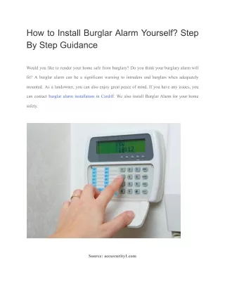
Burglar Alarm Leaving Certificate Technology
Stage 1 Use liquid solvent cement to join, Part 1 and Part 2 at 900 to make a corner of the box. Repeat procedure for the other 3 corners
A 2mm trim will be removed once the glue is dry Part 3 is over sized by 4mm in length and width Stage 2 Place the 4 sides on the bottom (3) and use the liquid solvent cement to glue on the bottom Repeat for top of box
45deg side is again over sized in length and width. Top edge corners are cut at 45deg using band saw Stage 3 Use the band saw to cut along each line so to remove the two corners . The 45deg sides are fixed on using liquid solvent cement.
Top fits on and off over the trim Fix part 5 and 6 inside box with liquid solvent cement. Stage 4 Use the band saw to cut along the 18mm line so you get the top and bottom of the box Glue the trim to the inside of the four side of the bottom half of the box.
Thyristor Cathode gate anode a g c Circuit Circuit is created in circuit wizard.
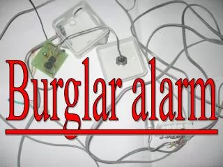
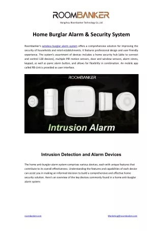
Toggle Switch Reed Switch Buzzer Power Supply Thyristor PCB 2k2 Resistor The circuit is then converted into a PCB and manufactured. 1M Resistor
Reed Switch Buzzer Toggle Switch Thyristor Power Supply PCB with electronic components
Thyristor is a lathing device. Once it is switched on by a small voltage at the gate it stays on. Buzzer is fixed to Alarm Housing using M3 Bolts Toggle Switch is fixed to the top of the alarm housing The Reed Switch will be fixed to the side of the Alarm Housing. How this is done will depend on the type of Reed Switch
Circuit Activation The Alarm hangs on a door with a magnet on the door frame so when the door opens the Reed Switch is activated by the magnet.