Download
1 / 31
310 likes | 439 Vues
This assignment covers key concepts in digital systems design, focusing on switch debouncing and the role of registers and latches. Switch debouncing is crucial for reliable operation in systems where mechanical switches are used, as bounce can lead to erroneous signals. The document illustrates simple debounce circuits and highlights the differences between various types of registers, including READ ONLY, READ/WRITE, WRITE ONLY, and those returning different values upon reading. Understanding these fundamentals is essential for effective digital system design.

E N D
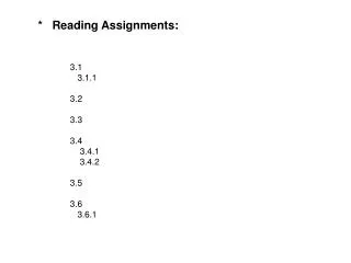
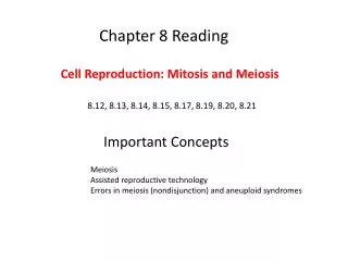
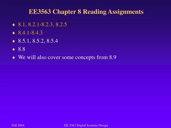
EE3563 Chapter 8 Reading Assignments • 8.1, 8.2.1-8.2.3, 8.2.5 • 8.4.1-8.4.3 • 8.5.1, 8.5.2, 8.5.4 • 8.8 • We will also cover some concepts from 8.9 EE 3563 Digital Systems Design
EE3563 Switch Debouncing • Every mechanical switch has some type of bounce • It is analogous to striking a hard surface with a hammer • With many common applications, switch bounce is not a problem • Flipping a light switch • Turning on a toaster • In applications where a count is taking place, or where a trigger signal is sent, switch bounce can cause errors • Solution: Design a circuit to prevent switch bounce • Called a “debounce” circuit EE 3563 Digital Systems Design
EE3563 Switch Debouncing • Simple debounce circuit is the bistable inverter circuit • The basic premise here is that the outputs will not change when the input is floating (i.e. not making contact) • When the switch is in the middle, nothing changes in this circuit, therefore, it is irrelevant how many times the switch makes/breaks contact with any side of the switch • Does anyone see a problem with this? EE 3563 Digital Systems Design
EE3563 Switch Debouncing • Not only is the input of the inverter pulled low, but so is the output of the other inverter • A Transistor-Transistor Logic (TTL) inverter has a pull-up resistor, so when its output is pulled low (from a high) momentarily, it can easily handle it • This circuit would be bad for high-speed CMOS • CMOS doesn’t use the pull-up resistors, so you briefly have virtual short-circuit to ground • This will not damage the circuit, but will cause a severe noise spike which can affect operation • It won’t cause damage because the time is so brief that there is no chance for heat to build-up EE 3563 Digital Systems Design
EE3563 Switch Debouncing • A debouncing circuit for high-speed CMOS is shown here • No outputs are shorted to ground • Uses 4 additional transistors in CMOS, as well as 2 resistors • Resistors on a chip take up space as well • Provides active low and high outputs EE 3563 Digital Systems Design
EE3563 Registers and Latches • A collection of two or more D-FFs with a common clock is often called a register • Often used to store related bits • May be unrelated bits though • May be control bits/flag bits/values • First microprocessors were called 4-bit because the register size was only 4 bits • Common size is 32 bits with 64 bit processors available • Registers may be • READ ONLY (to the user, written by other hardware) • READ/WRITE • WRITE ONLY • READ a different value than written EE 3563 Digital Systems Design
EE3563 Registers and Latches • READ ONLY Example • Two data registers may be used to add two values (as in your homework) • A third register may be used to “flag” the results • For example, logic could be placed on the output of the adder, and a register bit is set if the result is zero • Another register bit may be set if the result is negative • Another could be set if the result exceeds the adder capacity (carry out) • This register would be READ ONLY to the user, but is written by the system EE 3563 Digital Systems Design
EE3563 Registers and Latches • READ/WRITE Example • Similar in functionality to memory • The two registers that were added in the previous example could be wired as R/W, such that their individual values could be read EE 3563 Digital Systems Design
EE3563 Registers and Latches • WRITE ONLY Example • Could be used to control an output such as LED indicator lights • No reason to read the register as its value would not tell you the light is actually on • In the HW, the register that will be used to hold the digital value for the DAC is write only EE 3563 Digital Systems Design
EE3563 Registers and Latches • READ a different value than written • A register could be designed such that when reading it, a value completely independent of what was written is returned • This is not uncommon • A control register (such as the LED example) could be wired such that the user writes a value to activate the LEDs • The read value however, is a status indicator (perhaps wired to the actual LED output so that a true status can be obtained) • The point is that when dealing with a digital system, you can not ASSUME that a register behaves like memory EE 3563 Digital Systems Design
EE3563 Registers and Latches • A number of commercial registers and latches are available • The 74x175 has 4 D flip-flops • a CLK signal • a CLR_L signal • What is the purpose of the inverted inverter on the CLR_L signal? • Are these FF edge-triggered? • Do they have a postponed output? EE 3563 Digital Systems Design
EE3563 Registers and Latches • A number of commercial registers and latches are available • The 74x175 has 4 D flip-flops • a CLK signal • a CLR_L signal • What is the purpose of the inverted inverter on the CLR_L signal? • Buffer the input • Are these FF edge-triggered? • Yes • Do they have a postponed output? • No EE 3563 Digital Systems Design
EE3563 Registers and Latches • 74x175 EE 3563 Digital Systems Design
EE3563 Registers and Latches • 74x374 is an 8-bit register • Similar to the 74x175, but has a few differences • Does not have a CLR input • Does have an output enable • If the output is disabled, does it still latch values? EE 3563 Digital Systems Design
EE3563 Registers and Latches • 74x373 uses D latches instead of edge-triggered flip –flops • The outputs follow the inputs whenever C is asserted • It latches the current inputs whenever C is negated • Has an asynchronous CLR • Can clear regardless of clock signal • Also has Output Enable EE 3563 Digital Systems Design
EE3563 Registers and Latches • 74x377 is edge-triggered like the 374, but it has an input enable • Also called a gated clock EE 3563 Digital Systems Design
EE3563 Counters • A clocked sequential circuit whose state diagram contains a single cycle • A cycle is a path through a state diagram • The modulus is the number of states in the cycle • A modulus-m counter is also called a divide-by-m counter • Mod 4 would mean a counter that has 4 states • Generally, modulus refers to the remainder of a division • 5 mod 3 = 2 • A counter with a modulus that is not a power of 2 has extra unused states • Since n flip-flops have 2n states, any lower modulus results in unused states • Typically, T flip-flops are used in counters, but not always EE 3563 Digital Systems Design
EE3563 Counters • A ripple counter is similar to the ripple adder • Each flip-flop feeds into the succeeding flip-flop • The ripple counter suffers from slow speed since each output must propagate to the next flip-flop • Is this device synchronous or asynchronous? EE 3563 Digital Systems Design
EE3563 Counters • A synchronous counter has all flip-flops change on a common clock signal • This counter is called a synchronous serial counter because of the propagation from LSB to MSB EE 3563 Digital Systems Design
EE3563 Counters • A synchronous parallel counter is shown here • There is no need to wait for any propagation • As soon as the clock ticks, each FF toggles if enabled EE 3563 Digital Systems Design
EE3563 Counters • The 74x163 is a commercially available MSI counter • It is a synchronous 4-bit binary counter • It uses D FF, not T FF for its operation • This is done to facilitate load and clear functions • The counter can be reset to all zeros with one signal • The counter can be loaded with any initial value • These features make it extremely versatile • Each D FF is fed by a 2-input MUX that selects either the load input or the complement of the current input • The XNOR gates do the counting • There are also a couple of pins that can be used to hold its current state, a “pause” in the counting • There are numerous ways in which the 74x163 can be used EE 3563 Digital Systems Design
EE3563 74x163 Counter EE 3563 Digital Systems Design
EE3563 74x163 Counter • This configuration is in free-running mode; I.e. it is enabled continuously EE 3563 Digital Systems Design
EE3563 74x160/74x162 Decade Counter • The decade counters are configured to reset on the clock tick when the output is a decimal nine • The 74x163 could be wired this way as well, in fact, it can divide by any modulus up to 15 EE 3563 Digital Systems Design
EE3563 74x163 Counter • Here it is a mod-11 counter • When the RCO is asserted, indicating that a 15 has been reached, LD is also asserted, loading the counter with a 5 • Why a 5? EE 3563 Digital Systems Design
EE3563 74x163 Counter • What is the modulus of this counter? • What is the actual counting sequence? EE 3563 Digital Systems Design
EE3563 74x163 Counter • What is the modulus of this counter? • 11 • What is the actual counting sequence? • 0, 1, 2, 3, … 10, 0, 1, … EE 3563 Digital Systems Design
EE3563 74x163 Counter • This counter can also be cascaded using the RCO of the least significant counter to enable the most significant counter EE 3563 Digital Systems Design
EE3563 74x163 Counter • Another cascade configuration, this time a mod-193 • What is the start of the counting sequence? EE 3563 Digital Systems Design
EE3563 74x169 Counter • The 74x169 is a similar counter, however, it can count down as well as up • What is the value that must be placed on pin 1 to tell the x169 to count up? EE 3563 Digital Systems Design
EE3563 74x169 Counter • The 74x169 is a similar counter, however, it can count down as well as up • What is the value that must be placed on pin 1 to tell the x169 to count up? • We can’t tell from this symbol since both a high and a low are valid EE 3563 Digital Systems Design