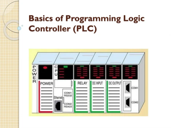
Basics of PLC Programming
Basics of PLC Programming. The PLC memory space can be divided into two broad categories: program files and data files Program files are the part of the processor memory that stores the user ladder logic program . Most instructions require one word of memory

Basics of PLC Programming
E N D
Presentation Transcript
The PLC memory space can be divided into two broad categories:program files and data files Program files are the part of the processor memorythat stores the user ladder logic program. Most instructionsrequire one word of memory The data files store the information needed to carry outthe user program. This includes information such as thestatus of input and output devices, timer and counter values,data storage Contents of the data table canbe divided into two categories: status data and numbers orcodes Processor Memory Organization
The S7-300 has three memory areas in CPU: Load memory System memory Work memory S7-300 Memory Organization
The load memory is located on a SIMATIC Micro Memory Card (MMC) It is used for storing code blocks anddata blocks, as well as system data (configuration, connections, moduleparameters etc.). It is possible to store the entire configuration data of project on MMC S7-300 Memory Organization: Load memory
The integrated CPU system memory is not expandable It contains: The address areas for memory bits, timers and counters The I/O process image Local data S7-300 Memory Organization: System memory
PII is a part of the program memory allocated to storing the on/off status of connected discrete inputs S7-300 Memory Organization: Process Input Image Connection of an open and closed switch to the PII through the input module
POI is that part of the program memory allocated to storing the actual on/off status of connected discrete outputs S7-300 Memory Organization: Process Output Image Connections of pilot lights to the output image table file through the output module
S7-300 Main memory The main memory is integrated in the CPU and cannot be extended It is used to execute the code and process user program data Programs only run in the main memory and system memory
S7-300 Retentivity of load memory, system memory, and main memory Retentive data in the load memory The program in the load memory is always retentive: It is stored on the SIMATIC Micro Memory Card, where it is protected against power failures or memory resets Retentive data in the system memory In configuration (Properties of CPU, Retenativity tab) must be specifed which part of memory bits, timers and counters should be kept retentive and which of them are to be initialized with "0” on restart (warm restart)
S7-300 Retentivity of load memory, system memory, and main memory Retentive data in the main memory The contents of retentive DBs are always retentive at restart and POWER ON/OFF Retentive data blocks can be uploaded to the main memory in accordance with the maximum limit allowed by the main memory Non-retentive DBs are initialized from the load memory with their initial values at restart or POWER ON/OFF Non-retentive data blocks and code blocks can be loaded in accordance with the maximum main memory limit
Program Scan PLC program scancycle
When a PLC executes a program, it must know—in real time—when external devices controlling a process are changing During each operating cycle, the processor reads all the inputs, takes these values, and energizes or de-energizes the outputs according to the user program This process is known as a program scan cycles Single PLC operating cycle consisting of the: Input scan Program scan Output scan Housekeeping duties (communications and diagnostics) Program Scan
Program Scan The time required to make a single scan can vary from about 1 millisecond to 20 milliseconds The scan time is a function of the following: The speed of the processor module The length of the ladder program The type of instructions executed The actual ladder true/false conditions
The For each rung executed, the PLC processor will: Examine the status of the Process Input Image table bits Solve the ladder logic in order to determine logical continuity Update the appropriate Process Output Image table bits, if necessary Copy the output image table status to all of the output terminals Copy the status of all of the input terminals to the input image table Program Scan
Program Scan: Data flow Overview of the data flow during the scan process
For each rung executed, the PLC processor will: Step 1 - Update the input image table by sensing the voltage of the input terminals. Based on the absence or presence of a voltage, a 0 or a 1 is stored into the memory bit location designated for a particular input terminal Step 2 - Solve the ladder logic in order to determine logical continuity. The processor scans the ladder program and evaluates the logical continuity of each rung by referring to the process input image table to see if the input conditions are met. If the conditions controlling an output are met, the processor immediately writes a 1 in its memory location, indicating that the output will be turned ON; conversely, if the conditions are notmet a 0 indicating that the device will be turned OFF is written into its memory location Program Scan
For each rung executed, the PLC processor will: Step 3 – Update the actual states of the output devices by transferring the output table results to the output module, thereby switching the connected output devices ON (1) or OFF (0). If the status of any input devices changes when the processor is in step 2 or 3, the output condition will not react to them until the next processor scan Program Scan
Program Scan: single rung program Scan process applied to a single rung program
Program Scan: multiple rung program Scan process applied to a multiple rung program
The standard IEC 61131 standardize five languages for programming PLC : Ladder Diagram (LD) — a graphical depiction of a process with rungs of logic, similar to the relay ladder logic schemes Function Block Diagram (FBD) — a graphical depiction of process flow using simple and complex interconnecting blocks Sequential Function Chart (SFC) — a graphical depiction of interconnecting steps, actions, and transitions Instruction List (IL) — a low-level, text-based language that uses mnemonic instructions. Structured Text (ST) — a high-level, text-based language such as BASIC, C, or PASCAL specifically developed for industrial control applications. PLC ProgrammingLanguages
PLC ProgrammingLanguages Standard IEC 61131 languages associated with PLC programming
The Ladder diagram language is the most commonly used PLC language and is designed to mimic relay logic PLC ProgrammingLanguages: Ladder diagram Equivalent ladder diagram (LD) program Hardwired relay control circuit
The Functional block diagram programming uses instructions that are programmed as blocks wired together on screen to accomplish certain functions. Typical types of function blocks include logic, timers, and counters PLC ProgrammingLanguages: Function Block Diagram Function block diagram equivalents to ladder logic contacts PLC ladder and equivalent function block diagram
Sequential function chart programming language is similar to a flowchart SFC programming is designed to accommodate the programming of more advanced processes PLC ProgrammingLanguages: Sequential Function Chart Major elements of a sequential function chart program
Structured text is a high level text language primarily used to implement complex procedures that cannot be easily expressed with graphical languages PLC ProgrammingLanguages: Structured Text PLC ladder and equivalent structured text program
Is closed when the bit value stored at the PII is equal to "1". When the contact is closed, ladder rail power flows across the contact and the result of logic operation (RLO) = "1” Otherwise, if the signal state at the PII is "0", the contact is open. When the contact is opened, power does not flow across the contact and the result of logic operation (RLO) = "0" Bit Logic Instructions: ---| |--- Normally Open Contact Examine If Closed instruction
Is closed when the bit value stored at the PII is equal to “0". When the contact is closed, ladder rail power flows across the contact and the result of logic operation (RLO) = "1” Otherwise, if the signal state at the PII is “1", the contact is open. When the contact is opened, power does not flow across the contact and the result of logic operation (RLO) = "0" Bit Logic Instructions: ---| / |--- Normally Closed Contact Examine If Opened instruction
This instruction looks and operates like a relay coil and is associated with a POI memory bit. This instruction signals the PLC to energize (switch on) or de-energize (switch off ) the output Bit Logic Instructions: ---( ) Output Coil Output Coil energize instruction
Those addresses indicates what PLC input is connected to what input deviceand what PLC output will drive what output device Addressingformats can vary from one PLC family to another as wellas for different manufacturers The assignment of an I/O address can be included inthe I/O connection diagram Bit Logic Instructions Addressing I/O connection diagram
Bit Logic Instructions Addressing Addressing format for Siemens S7-300
Branch instructions are used to create parallel paths ofinput condition instructions. This allows more than onecombination of input conditions (OR logic) to establishlogic continuity in a rung Multiple Branch: OR Instruction Typical branch instruction
Input and output branches can be nested to avoidredundant instructions and to speed up processor scantime Multiple Branch: OR Instruction Nested contact program
Most PLCs have an area of the memory allocated for whatare known as internal storage bits. These storage bits arealsocalled internal outputs, internal coils, internal controlrelays, or simply internal memory bits (M-memory) Internal Relay Instructions Programmed internal relay control
A processor has basically two modes of operation: theprogrammode and some variation of the runmode Program Mode is used to entera new program, edit or update an existing program,upload files, download files, document (print out) programs,or change any software configuration file in theprogram. When the PLC is switched into the programmode, all outputs from the PLC are forced off regardlessof their rung logic status, and the ladder I/O scansequence is halted Run Mode is used to execute the userprogram. Input devices are monitored and output devicesare energized accordingly. After all instructionshave been entered in a new program or all changesmade to an existing program, the processor is put inthe run mode Modes of Operation
Test Mode is used to operate or monitorthe user program without energizinganyoutputs. The processor still reads inputs, executesthe ladder program, and updates the output statustable files, but without energizing the outputcircuits Remote Mode allows the PLC to be remotely changedbetween program and run mode by a personal computerconnected to the PLC processor. The remotemode may be beneficial when the controller is in alocation that is not easily accessible Modes of Operation Three-position keyswitch used to selectdifferent processor modes of operation