Download
1 / 16
170 likes | 694 Vues
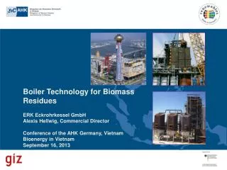
Boiler Technology for Biomass Residues ERK Eckrohrkessel GmbH Alexis Hellwig , Commercial Director Conference of the AHK Germany, Vietnam Bioenergy in Vietnam September 16, 2013 . History and references. Eckrohr boiler technology was developed in the mid 1940s

E N D
Boiler Technology for Biomass Residues ERK Eckrohrkessel GmbH Alexis Hellwig, Commercial Director Conference of the AHK Germany, VietnamBioenergy in Vietnam September 16, 2013
History and references • Eckrohr boiler technology was developed in the mid 1940s • first licensees started to build Eckrohr-boilers worldwide; ERK offers engineering only • outsourcing of the ERK technology from La Mont Kessel GmbH in 1977 • today more than 30 licensees worldwide (from small boiler manufacturers to turn-key suppliers for example in Thailand BIB, Getabec and DGA) • >5.900 boiler and heater references with thermal outputs of 0.3-250MWth all over the world • references for biomass (>450), waste (>580), cogeneration (>200), fuel mixtures (>350) as well as coal, oil and gas (>4,000) Background of Eckrohrkessel
Licensees all over the world (currently 31) Background of Eckrohrkessel
Conversion technologies fuels Energy From Biomass combustion (grate and fluidised bed) gasification • ERK has references for all aforementioned conversion technologies • choice of firing system depends on fuel quality, process and efficiency requirements as well as commercial constraints
Target of efficient combustion 1.) total burnout of fuel no carbon content in the ash no CO or pyrolytic gases in the flue gas for higher efficiency and environment 2.) low NOx emission in flue gases, less effort for secondary DeNOx treatment for the environment 3.) low dust content in flue gases less fouling and corrosion in the boiler for a higher availability of the boiler Energy From Biomass
meltic eutectic with corrosion Grate System With Boiler evaporator economiser fine dust secondary air superheater secondary air high temperature corrosion slagging
Advantages: • very low demands to fuel treatment • Disadvantages: • cooled mechanical grate for higher calorific values • (higher plant and operation costs) ( scuffing of grate bars) • smooth packed bed hard to ensure • areas with cold streaks with CO and high dust loads • higher central excess air for sufficient burnout • → boiler and flue gas treatment unit larger due to type of incineration (excess air) Grate System With Boiler
Gasification – Two Stage Combustion Energy From Biomass Principle: • generation of carbon monoxide and hydrogen under sub-stoichiometric conditions in the first stage (gasifier) • high temperature combustion in the second stage (torsional chamber) • low gasification temperatures keep complicated fuels, e.g. chlorine and potassium, in the ash, thus reducing fouling and corrosion Advantages • higher steam parameters due to absence of complicated substances; higher plant efficiency • reduced maintenance & small plant components • low investment and complexity Disadvantages • not proven for highly contaminated wood waste yet • no existing references larger 70 MWth yet
excess air: ~ 0,5 excess air: 1,4 NOx high temperature combustion excess air: 1,2 Direct Relation of Two Systems DeNOx alkaline condensation (Na, K) CO streak low temperature CO streak low temperature gases to burner controlled burnout high velocity with high dust content (alkaline metals: Na, K) gasifier hight air fuel ash low dust content ash cooling cool ashes air high ash heat loss fuel air pre- heating air for carbon burnout airfordegasify-ingandpyrolysis airfordrying air for drying air for gasifying and pyrolysis air for carbon burnout in ash
Advantages of Counter Current Flow Gasification • Spatial separation of drying and gasification from the combustion process leads to uniform flue gas burnout. • Little excess air (20 %) in the subsequent combustion system leads to a smaller boiler (~25 %) and a smaller flue gas treatment unit. • Simpler and more robust gasification reactor less prone to interference • Little loss of fuel due to extremely low carbon levels in the ash and cold ash removal • Concentration of nitrous oxide in the flue gas at a minimum even at a high concentration in the fuel due to low gasification temperature • Low levels of dust and contaminants, since the gasifier‘s fixed bed serves as a filter in the counter flow • → higher efficiency factor for the entire plant, since the boiler runs with higher steam parameters at low facility costs
Gasification references Energy From Biomass • >100 references for biomass gasification plants (1-70MWth) • Simple scale-up to 40MWel • >40MWel plants possible, but unusual for biomass; gasifier adaptation necessary MWth 5 25 40 70 130
Prof. Dr.-Ing. UdoHellwig, General Manager • p: +49 30 8977 46-0 • e: uhellwig@eckrohrkessel.com Alexis Hellwig (M.A.), Commercial Director • p: +49 30 8977 46-0 • e: ahellwig@eckrohrkessel.com Address: • Am Treptower Park 28-30 • Schuckert-Höfe, Haus A • 12435 Berlin • Germany • www.eckrohrkessel.com Contact