Download

1 / 19
190 likes | 372 Vues
Thermoelectric Heat Pump Geothermal Scale Model. E. Kimball Perley March 2013 ELM Senior Projects. What is Geothermal Heating?. Extracts heat from the ambient ground temperature Can be closed or open loop Can run off well water or an installed ground loop. Traditional Heat Pumps.

E N D
Thermoelectric Heat Pump Geothermal Scale Model E. Kimball Perley March 2013 ELM Senior Projects
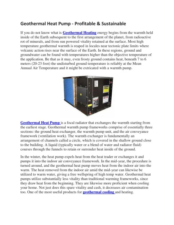
What is Geothermal Heating? • Extracts heat from the ambient ground temperature • Can be closed or open loop • Can run off well water or an installed ground loop
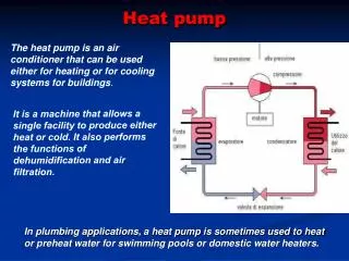
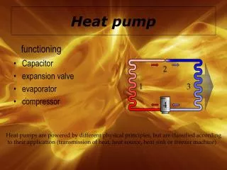
Traditional Heat Pumps Expansion Valve Evaporator Heat moves from the hot side to the cold side, this is Q Condenser Compressor The compressor is powered with electricity.
Thermoelectric Modules • When a thermoelectic module is powered, it acts as a heat pump. • One side becomes warmer and the other cooler based on the polarity of the power. Heat moves from the hot side to the cold side, this is Q The module is powered with electricity. Hot Side Your Home Cold Side Ground Water
Coefficient of Performance Q Heat Moved COP = Power into pump Electric Heat has a natural COP of 1 Traditional Geothermal has a COP of >1 Thermoelectric COP is dependent on the operating range
The Advantages of Thermoelectrics • No moving parts • Ease of maintenance • Quiet • Scalable • Ease of Installation • Variable heat transfer
Client Requirements • Table top scale model • Uses a thermoelectric heat pump • Takes heat from tap water at constant flow • Transfers heat to hot water tank • Maintains hot tank temperature at 100-110 Fahrenheit • Controls the power to the thermoelectric module
System Diagram Sensor Connection Lab View Interface Temperature Sensors Wiring Connection Labeling Indicator National Instruments Sensor Box Power Supply & Control Circuit Water in Flow regulator Thermoelectric Module Flow out Cold Water Tank Hot Water Tank Aluminum Heat Spreaders
COP Requirements Max DT for COP > 1; 34 C Max DT for COP > 1 at 1.5 A; 22C System power must increase as DT increases to maintain maximum COP
Sizing Calculations 20 Watts = 20 J/s 20 J/s * .238cal/J = 4.78 cal/s 4.78 cal/s * 3600 s/h = 17208 cal/h 20 Watts 17208 cal/h / 1000ml/l = 17C/h 8 Watts Moving 20 Watts of heat in an hour this module could raise the temperature of 1 liter of water by 17C.
Mechanical Design • The system will use a module from HiZ • The Hot and cold water tanks will be constructed from PVC • Insulation will prevent heat loss Water in Flow regulator Thermoelectric Module Flow out Cold Water Tank Hot Water Tank Aluminum Heat Spreaders
Mechanical Design Cont. • Two square braces will be used to bolt the cold and hot water tanks together with the module in between. • Support and pressure from these braces will keep the module and it’s heat sinks secure. Images of model without insulation.
Software Design • The entire system will be controlled by a Lab View user interface. • The computer will both record all of the relevant data and calculate derived values such as power and COP • The user will need to input some data and turn the system on and off • The software will drive the module at a current dependent on the Dt of the system to increase performance. Lab View Interface National Instruments Sensor Box
SoftwareDiagram Start System Tank is Hot Current = 0A LEDs =0,1,0 Th<30? System on Th>33? DT>30? OR DT>24? Heating Stage 1 Current = 1.5A LEDs=1,0,0 Heating Stage 2 Current = 3.0A LEDs=1,0,0 Yes Cold Water Error Current = 0.0A LEDs=0,0,1 Tc<3?
User Interface Required User Input Efficiency of System
Electrical Design National Instruments Sensor Box Power Supply & Control Circuit Temperature Sensors Thermoelectric Module The National Instruments sensor box will power and read all four temperature sensors. It will also use 0-5 Volts to drive the power control circuit for the module. It will take readings of the power circuit to calculate the power being used. These readings are all necessary for the COP and other calculations done by the software.
Power Control Circuit • A Power MOSFET transistor will control the flow of current through the Module. • Increasing the Voltage into the Gate of the MOSFET allows more current to flow, increasing the power to the Module Power Supply (25 Watts) Thermoelectric Module MOSFET 0-5v Signal from NI sensor box D G S
Budget Other components: Power supply NI USB 6008 Laptop Computer Flow controllers Miscleds, resistors, sensors, transistors, wiring