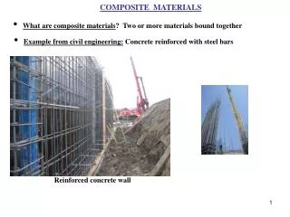
Composite Materials and Wreckage Examination
120 likes | 351 Vues
Composite Materials and Wreckage Examination. Matthew R. Fox, Ph.D. Composite Layers. Vertical Stabilizer and Rudder. Vertical Stabilizer (Internal Structure). Rudder Hinge. Rudder. Main Attachment Fittings (Lugs). Left Front Fracture. Visual and Fractographic Examination. Ultrasound NDI.

Composite Materials and Wreckage Examination
E N D
Presentation Transcript
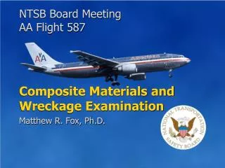
NTSB Board Meeting AA Flight 587 Composite Materials and Wreckage Examination Matthew R. Fox, Ph.D.
Composite Layers Vertical Stabilizer and Rudder Vertical Stabilizer (Internal Structure) Rudder Hinge Rudder Main Attachment Fittings (Lugs)
Left Front Fracture • Visual and Fractographic Examination Ultrasound NDI • Nondestructive Inspection (NDI) • Materials Testing and Microstructural Examination Microstructure 2 mm Examination Methods • Lug Tests
Visible Damage Visible damage observed at rudder hinge line and lug locations. Left Center Left Rear • Some lug pieces remained attached to the fuselage. Right Rear
Fractographic Examination • Composite fractures examined at high magnification using scanning electron microscopy • Lug area fractures photographed at more than 300 locations • Over 500 square inches of crack surfaces examined at high magnification • No fatigue observed Methods and Results NTSB Board Meeting AA Flight 587
Tension Fracture Pattern Left Lugs Right Lugs Vertical stabilizer cross-section as viewed from behind
Fracture Pattern Bending Tension Tension Left Lugs Right Lugs Vertical stabilizer cross-section as viewed from behind
Fracture Pattern Bending Bending Tension Tension Left Lugs Right Lugs Vertical stabilizer cross-section as viewed from behind Consistent with overload bending to the left
Right Rear Lug Fracture Load • Structural analysis predicted fracture initiation at the location circled in red. • Structural analysis was consistent with damage observed. FWD
Lug Tests Test Lug FWD Accident Lug Load Load Fracture pattern for the accident right rear lug was as expected given the accident loads.
Summary • Composite structure was manufactured as expected. • No evidence of preexisting damage was observed. • Damage patterns were consistent with an overload failure in bending to the left. NTSB Board Meeting AA Flight 587
National Transportation Safety Board American Airlines Flight 587 Belle Harbor, New York November 12, 2001 NTSB Board Meeting October 26, 2004