Clutch
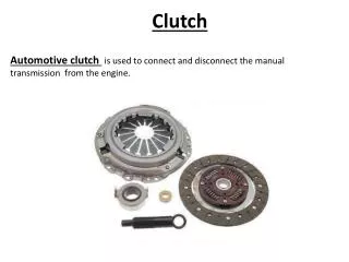
Automotive clutch is used to connect and disconnect the manual transmission from the engine. Clutch. Clutch release mechanism – cable, linkage or hydraulic system allows the driver to disengage the clutch when using foot pedal. Clutch Parts. Slave Cylinder.


Clutch
E N D
Presentation Transcript
Automotive clutch is used to connect and disconnect the manual transmission from the engine. Clutch
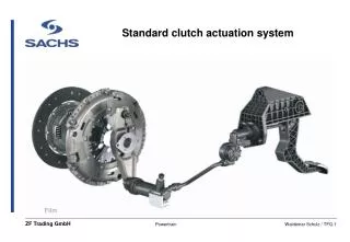
Clutch release mechanism – cable, linkage or hydraulic system allows the driver to disengage the clutch when using foot pedal. Clutch Parts Slave Cylinder Master Cylinder – any leak in the hydraulic system will prevent the clutch pedal from coming back up. Takes brake fluid. Cable
Clutch Fork – lever that forces the release bearing into the pressure plate. Clutch Parts
Release/throw out bearing – bearing that reduces friction between the clutch fork and the pressure plate. • Dry or worn bearing will cause a squeal when stepping on the clutch pedal, worse on a cold day. Clutch Parts
Pressure plate – spring loaded device that presses the clutch disc against the flywheel. Two types – Coil spring and Diaphragm type. Clutch Parts
Clutch Disc – Friction disc (same material as brakes) splined to the transmission. There should never be any oil or grease on the clutch parts. Clutch Parts Clutch facing springs – are use to cushion disc when it engages.
Flywheel – provides a mounting place for the clutch and friction disc assembly. • Flywheels are made from hardened steel (brake rotors). • Ring gear around the flywheel can be replaced. • Grind if cracks (over heating), grooves, or glazed. • Warped flywheel will cause pulsation in clutch pedal and may grab at acceleration. Clutch Parts
Pilot Bearing – bushing or bearing that supports the forward end of the transmission input shaft. Clutch Parts
Grabbing clutch – vibration or jerking on takeoff. Cause: Engine mount, friction plate, pressure plate, flywheel. Dragging Clutch – transmission grind when trying to shift or engage clutch. Cause: too much pedal free play, warped or bent friction disc, oil or grease on the friction disc. Clutch slippage – RPMs go up, but the vehicle doesn’t move. Cause: Worn friction disc, miss adjustment of the clutch cable. Clutch Problems
Transmission input shaft – a shaft, operated by the clutch (engine), that turns the gears inside the transmission. Transmission Gears – provide a means of changing output torque and speed. Synchronizers – devices for meshing gears into engagement and prevent grinding. Shift forks – pronged units for moving synchros on there shafts for gear engagement. Manual Transmission
Shift linkage – arms or rods that connect the shift lever to the shift forks. Gear shift lever – lever allowing the driver to shift gears. Two types –Internal and external. If out of adjustment might cause grinding. Output shaft – shaft that transfers rotating power out of the transmission to the driveshaft. Transmission case – housing that encloses transmission shaft, gears, and lubricating oil. Counter shaft – Gears on this shaft are attached to the output shaft. Manual Transmission
Neutral – all the synchronizer sleeves are located in the center. Input shaft turns and output shaft is stationary. Neutral
1st Gear (4.36:1) – Synchronizers engage to the first output gear. Small gear on countershaft drives a large gear on output shaft giving high torque and low speed. 1st Gear
2nd Gear (2.52:1) – 1/2 gear synchronizer is moved away from the first gear and engaged to the second gear. This provides less torque, but more speed than the first gear. 2nd Gear
3rd Gear (1.51:1) –3/4 synchronizer is moved to engage the third gear (1/2 synchronizer is in neutral). 3rd Gear
4th gear (1:1) – 3/4 synchronizer is moved to engage the fourth gear. The synchronizer sleeve locks the input shaft directly to the output shaft. No torque multiplication. 4th Gear
5th Gear/Overdrive gear (0.87:1) – Keeps the engine speed down at highway speeds to increase fuel economy. 5th Gear
Reverse gear (4.02:1) – Synchronizer is moved onto reverse gear on the output shaft. Power flows through the counter shaft, reverse idler gear (changes the direction), reverse gear, and to the output gear. Reverse light switch is engaged at the same time. Reverse Gear
Takes 80W – 90W, also called synchro oil. If low on oil, might cause noises. Transmission Gear oil
A gear (worm) is attached to the output shaft to drive the Speedo meter. Speedo meter Gear