Data Communications
620 likes | 742 Vues
Asynchronous Transfer Mode (ATM) is a high-speed, connection-oriented network technology designed to handle both real-time and non-real-time data efficiently. Operating at speeds up to 622 Mbps, ATM uses fixed-sized packets called cells to maintain low-latency transmission, ensuring data arrives in order. Key features include support for multiple logical connections, reduced overhead, and virtual circuit creation. ATM architecture includes user, control, and management planes, enabling effective communication between end-users and networks. This technology is pivotal for applications that demand high performance and reliability.

Data Communications
E N D
Presentation Transcript
Data Communications Asynchronous Transfer Mode and Frame Relay
What is ATM? • A packet switched, connection-oriented service • Local area, metro area, and wide area service • Can support real-time traffic and non-real-time traffic (data arrives in order, low delay) • Can support various levels of service (continuous, variable, available, and unspecified) • Very fast (up to 622 Mbps) • A complex technology and typically expensive
More What is ATM? • Similarities between ATM and packet switching • Transfer of data in discrete chunks • Multiple logical connections over single physical interface • In ATM flow on each logical connection is in fixed sized packets called cells • Minimal error and flow control • Reduced overhead • Data rates - 25.6Mbps to 622.08Mbps (155.5 Mbps necessary for full-motion video)
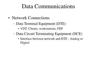
Overview of ATM Network • ATM is similar to IP – a mesh network of “routers” (ATM switches) • Two types of links in ATM • NNI (network – network interface) connects two ATM switches; UNI (user – network interface) connects switch to user device • ATM is connection-oriented • User must create a virtual circuit thru the ATM network (using virtual circuit ID); signals create circuit, maintain circuit, dissolve circuit
Protocol Architecture • User plane • Provides for user information transfer along with flow control and error control • Control plane • Performs call and connection control functions • Management plane • Plane management • Management functions related to system as a whole; make sure the various planes coordinate their activities properly • Layer management • Provides operations, administration, and maintenance (OAM) services thru info packets that switches exchange to keep system running effectively
Protocol Architecture • Physical plane • Designed to run over SONET but can also run over FDDI, T-1, and T-3 • ATM Layer • Defines the cell format and how to respond to info found in the header. Also responsible for setting up and releasing connections, and performs congestion control • ATM Adaptation Layer (AAL) • Provides the interface between applications and the ATM layer
ATM Logical Connections • Virtual channel connections (VCC) • Analogous to virtual circuit in X.25 • Basic unit of switching between two end users • Full duplex • VCCs used for data, user-network exchange (control), and network-network exchange (network management and routing)
ATM Logical Connections • Two types of virtual circuits • Permanent virtual circuit – analogous to a leased telephone line • Switched virtual circuit – created using a connection protocol based on ITU-T Q.2931 • Virtual path connection (VPC) • Bundle of VCCs with the same end points
Advantages of Virtual Paths • Simplified network architecture • Network transport functions can be applied to a channel or a path of channels • Increased network performance and reliability • Network deals with fewer entities • Reduced processing and short connection setup time • Much work is setting up path, reserving capacity for future channels • Enhanced network services • Path is used internally but also visible to user
What Are VCCs Used For? • Between end users • Used to carry end to end user data, control signals • VPC provides overall capacity, VCC organization done by users • Between end user and network • Used to carry control signaling between user and network (typos top of page 353 – VPC should be VCC) • Between network entities • Used to carry network traffic management and routing information
Control Signaling – VCC • Done on separate connection ; Four methods for establishing a VCC: • Semi-permanent VCC – no control signaling necessary • Meta-signaling channel - used as permanent control signal channel – this channel is used to set up other VCC signaling channels between user and network • User-to-network signaling virtual channel – Used for control signaling - Used to set up VCCs to carry user data • User-to-user signaling virtual channel • Within pre-established VPC • Used by two end users without network intervention to establish and release user-to-user VCC
ATM Cells • Fixed size • 5 octet header (cell tax) • 48 octet information field • Why so small? • Small cells reduce queuing delay for high priority cells • Small cells can be switched more efficiently • Easier to implement switching of small cells in hardware • Fixed-size makes programming more easy
Header Format • Generic flow control • Used at user to network interface • Controls flow of data from user device into the ATM network only • Essentially two classes of connections – controlled and uncontrolled • Controlled – network provides info to user regarding how many cells it can send – like a credit mechanism for flow control • Uncontrolled – network simply enables or disables sending of cells – like X-ON/X-OFF flow control
Header Format • Virtual path identifier • An 8-bit (UNI) or 12-bit (NNI) path ID • Virtual channel identifier • A 16-bit channel ID. Together, VPI and VCI identify a logical connection • Payload type • Various types of user info or network management info • For example: leftmost bit identifies payload as user data or OAM info; second bit indicates whether cell has passed thru any congested switches; third bit might be used to indicate last cell in a sequence of cells
Header Format • Cell loss priority • CLP bit indicates a cell’s priority level • If congestion occurs, ATM has option of deleting cells to relieve congestion. Cells with CLP = 1 go first. • Header error control • See the following slides
Header Error Control • Provides for error checking on the header only • Payload is unprotected. Is this a good idea? • Fiber optic used – so low error rates • Some other layer can error detect the payload • Does it really make sense to error detect real-time traffic? • ATM needs the speed! • Uses x8 + x2 + x + 1 checksum • Allows some error correction (single-bit errors, which AT&T says happens 99.5% of time)
Header Error Control • HEC can also be used for providing synchronization • Apply error-checking method using 40 consecutive bits. If it does not generate a result consistent with the last 8 bits, shift one bit and try again. • Repeat above step until a consistent result is found. Could it be a coincidence? Try it three more times. All four succeed? You are in sync.
ATM Service Categories • An ATM network can support many types of traffic: • Real time • Constant bit rate (CBR) • Real time variable bit rate (rt-VBR) • Non-real time • Non-real time variable bit rate (nrt-VBR) • Available bit rate (ABR) • Unspecified bit rate (UBR)
CBR • Fixed data rate continuously available • Tight upper bound on delay • Can support uncompressed audio and video • Video conferencing • Interactive audio • A/V distribution and retrieval • Tightly controlled by Peak Cell Rate (PCR), Cell Transfer Delay (CTD), and Cell Delay Variation (CDV) • $$$$
rt-VBR • Time sensitive application • Tightly constrained delay and delay variation • rt-VBR applications transmit at a rate that varies with time • Examples include bursty voice and video • Can statistically multiplex connections • Parameters include Peak Cell Rate, Sustainable Cell Rate, and Maximum Burst Size • $$$
nrt-VBR • Non-real time VBR • Intended for bursty traffic with no tight constraints on delay and delay variation • Examples include airline reservations, banking transactions • Parameters include Peak Cell Rate, Sustainable Cell Rate, Maximum Burst Size, Cell Loss Ratio, Cell Transfer Delay • $$$
ABR • Application specifies Peak Cell Rate (PCR) and Minimum Cell Rate (MCR) • Resources allocated to give at least MCR • Spare capacity shared among all ABR sources • Examples include LAN interconnection and basic critical data transfer systems such as banking, defense information • (flying standby) • $$
UBR • For application that can tolerate some cell loss or variable delays (non-critical apps) • Cells forwarded on FIFO basis • Do not specify traffic related service guarantees • Examples include text/data/image transfer, messaging, remote terminals • Best effort service (wear your parachute) • $
ATM Adaptation Layer • Essentially the “translation layer” between ATM layer and other layers, such as PCM and IP: • PCM (voice) • Assemble bits into cells • Re-assemble into constant flow • IP • Map IP packets onto ATM cells • Fragment IP packets • Use LAPF over ATM to retain all IP infrastructure
Adaptation Layer Services • Handle transmission errors • Segmentation and re-assembly • To enable larger blocks of data to be carried in the information field of ATM cells • Handle lost and misinserted cells (cells routed the wrong way) • Perform flow control and timing control
Supported Application types • Four AAL protocols defined: • AAL 1: CBR traffic, e.g. circuit emulation (T-1 over ATM), voice over ATM, real-time video • AAL 2: rt-VBR traffic, e.g. MPEG voice and video • AAL 3/4: nrt-VBR traffic, e.g. general data service (not really used by anyone) • AAL 5 (successor to AAL 3/4): e.g. nrt-VBR: voice on demand; nrt-VBR: frame relay, ATM; UBR: IP over ATM
AAL 1 • AAL 1 is the interface between a real-time uncompressed byte stream and ATM • Got to be fast! • No convergence sublayer, only SAR sublayer • AAL 1 takes 46 or 47 bytes of data and puts a one or two byte header on front
AAL 1 continued • AAL 1 header consists of following: • One bit pointer – tells whether this is a one byte header or a two byte header. If second byte is included, this byte tells where the data starts within the payload (in case the payload does not contain a full 46 bytes of data) • Three-bit sequence number – used to tell if a cell is lost or mis-inserted (which may be too late anyway for real-time) • Four bits of error checking on preceding 3-bit sequence number (yikes!)
AAL 2 • AAL 2 format is used for compressed data, which needs to indicate where each frame of compressed data ends and begins • Similar to AAL 1 – no convergence sublayer, only the SAR sublayer • Unlike AAL 1, AAL 2 adds a header and a trailer
AAL 2 continued • The AAL 2 format has the following fields: • Sequence number – same as AAL 1 • Type field – helps identify message boundaries by indicating when a cell corresponds to the first, last, or intermediate cell of a message • Length field – specifies the number of bytes in the payload • Checksum – applied to the entire cell, including the data!
AAL 5 • AAL 5 packets can be very large – up to 65,535 byte payload • AAL 5 not designed for real-time traffic • SAR sublayer takes the potentially large convergence sublayer packets and breaks them into 48 byte chunks, ready for the ATM layer • SAR sublayer also adds a 32-bit CRC at the end of the packet, which is applied to the entire packet (see next slide for example)
Frame Relay • What is it? • A high-speed communications technology that is used in hundreds of networks throughout the world to connect LAN, SNA, Internet, and even voice traffic. • Designed to be more efficient than X.25 • Developed before ATM • Larger installed base than ATM • ATM now of more interest on high speed networks
Recall X.25 • Call control packets, inband signaling • Multiplexing of virtual circuits at layer 3 • Layer 2 and 3 include flow and error control • Considerable overhead! • Not appropriate for modern digital systems with high reliability
Frame Relay - Differences • Call control carried in separate logical connection • Multiplexing and switching at layer 2 • Eliminates one layer of processing • No hop-by-hop error or flow control • End-to-end flow and error control (if used) are done by higher layer • Single user data frame sent from source to destination and ACK (from higher layer) sent back
Advantages and Disadvantages • Lost hop-by-hop error and flow control • Increased reliability makes this less of a problem • Streamlined communications process • Lower delay • Higher throughput • Tulsa, OK to NYC and back: • X.25: 1 sec delay round trip • Frame relay: 70 msec delay round trip
Control Plane • Between subscriber and network • Separate logical channel used • Similar to common channel signaling for circuit switching services • Data link layer • LAPD (Q.921) • Reliable data link control • Error and flow control between user (TE) and network (NT) • Used for exchange of Q.933 control signal messages
User Plane • End to end functionality • Transfer of info between ends • LAPF (Link Access Procedure for Frame Mode Bearer Services) Q.922 • Frame delimiting, alignment and transparency • Frame mux and demux using addressing field • Ensure frame is integral number of octets (zero bit insertion/extraction) • Ensure frame is neither too long nor short • Detection of transmission errors • Congestion control functions
Frame Fields • DLCI – Denotes the port to which the destination LAN (or device) is attached • The routing tables at each intervening frame relay switch use the DLCI to route the frames to the proper destination • FECN and BECN – Congestion control techniques • DE – Discard Eligibility bit – Have you exceeded your data rate + burst rate for more than two seconds?
Frame Relay Operation • Each frame relay switch performs following: • 1. Check integrity of frame (FCS) • 2. Look up DLCI in a table • 3. Relay frame out appropriate port or trunk
Any Problems? • Just discard the frame! • Frame check error? Discard frame • Congestion? Discard frame • Invalid DLCI? Discard frame • Who informs the sender that a frame was discarded? • Not frame relay! (Let TCP do it)