Download
1 / 10
130 likes | 529 Vues
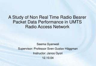
UMTS Terrestrial Radio Access Network Architecture. Raul Bruzzone. UMTS Architecture. A UMTS System comprises three main parts: Core Network (CN) UMTS Terrestrial Radio Access Network (UTRAN) The User Equipment (UE). CN. Iu. UTRAN. Uu. UE. UTRAN.

E N D
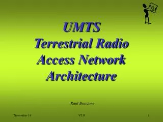
UMTS Terrestrial Radio Access Network Architecture Raul Bruzzone V2.0
UMTS Architecture A UMTS System comprises three main parts: • Core Network (CN) • UMTS Terrestrial Radio Access Network (UTRAN) • The User Equipment (UE) CN Iu UTRAN Uu UE UTRAN UMTS Terrestrial Radio Access Network CN Core Network UE User Equipment Raul Bruzzone
System Domains Home Network Domain [ Zu] Cu Uu [ Yu] Iu Serving Transit Network Network Domain Domain USIM Mobile Access Core Domain Equipment Network Network Domain Domain Domain User Equipment Infrastructure Domain Domain ETSI
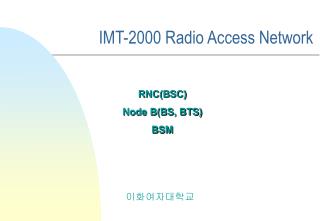
Structure of the UTRA Network Core Network Iu Iu RNS RNS Iur Cells Source: ETSI
UMTS Radio Network Controller Iu RNS RNC Iur Iur Iub Iub Node B Node B Cells Source: ETSI
Serving and Drift Radio Access Networks Core Network Iu Iu DRNS SRNS Iur Cells UE Source: ETSI
Core Network Core Network Iu Iu Iu Iu DRNS SRNS SRNS RNS Iur UE UE Before SRNS Relocation After SRNS Relocation Streamlining of the UTRAN - Core Network Connection Source: ETSI
CSE HLR CAP MAP A ISUP ISUP MSC G-MSC N-ISDN GSM BSS IP IP G b SGSN GGSN IP networks X.25 UMTS Segment IWU IWU X.25 1A 1Gb UTRAN I u Evolution of the GSM Network towards the UMTS Network:Starting Point (2002) ETSI
Evolution of the GSM Network towards the UMTS Network:Introduction of a UMTS Core Network (2005 ?) CSE HLR CAP MAP ISUP A ISUP MSC G-MSC N-ISDN GSM BSS IP IP G b SGSN GGSN IP networks X.25 UMTS Segment IWU IWU X.25 1A 1Gb UMTS CN UTRAN I u ETSI
Terrestrial Radio Access Network ArchitectureSummary • UMTS is composed of Core Network, Radio Access Network and User Equipment. • The Radio Access Network (UTRAN) handles radio link connections, enabling Base Station handover. • Handover management is done at the UTRAN Controller. • The UMTS Fixed Network will evolve from the GSM Network model, following several phases. Raul Bruzzone