Vertical-flexure CCD module: Thermal and Dynamic FEA
This presentation details the thermal and dynamic finite element analysis (FEA) of a vertical-flexure CCD module, addressing the challenges posed by the molybdenum-invar CTE mismatch. The objectives include demonstrating acceptable thermal stresses within survival temperature ranges and achieving suitable modal performance. Key findings indicate low thermal stresses and high resonant frequencies with non-optimized TZM flexures. Future work will focus on determining optimal flexure dimensions to minimize stress while maximizing the first resonant frequency.

Vertical-flexure CCD module: Thermal and Dynamic FEA
E N D
Presentation Transcript
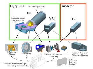
Vertical-flexure CCD module:Thermal and Dynamic FEA Bruce C. Bigelow University of Michigan Department of Physics 10/28/04
Vertical-flexure CCD module Objectives: • Accommodate Moly-Invar CTE mismatch with vertical flexure Moly CCD mount (see previous presentation) • Demonstrate acceptable thermal stresses for package over survival temperature range • Demonstrate acceptable modal performance for package
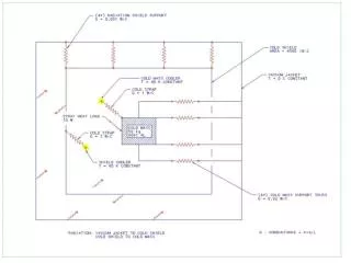
Vertical-flexure module FEA Analyses: • Neglect AlN, silicon from models (TZM and Invar only) • No pre-stress of package at room temp • TZM Flexure geometry (not optimized): • Blade thickness = 0.4 mm (0.016”) • Blade width = 8 mm (0.32”) • Blade effective length = 4 mm (0.16”) • Thermal: • Simple delta-T = -160K, constant CTEs • Frame constrained for zero mounting stress • Dynamic: • Mounting pads constrained • TZM Flexure to Invar joint nodes coupled
Vertical-flexure module FEA Analyses: • Thermal: • Simple DT = -160K, constant CTEs • Frame constrained for zero base stress at mounting • Flexures and Invar base interface nodal deflections coupled at centerline to simulate single screw constraints (very conservative – neglects screw head constraint) • Z constraints coupled at top of Invar surface (worst case)
CCD module FEA – frame stress Max stress in flexures – 132 MPa – 19,410 PSI (TZM Sy = 860 MPa)
CCD module FEA – Invar stress Max stress in Invar – 5.6 MPa – 812 PSI (Invar Sy = 300 MPa)
CCD module FEA - elements Max distortion of Invar base (CCD mounting surface) is 0.1 micron
Vertical-flexure module FEA Analyses: • Dynamic: • Modal analysis, reduced (Householder) modal extraction • TZM - Invar interface nodal deflections coupled as in thermal case • First 10 frequencies: • SET TIME/FREQ • 1 3279.8 • 2 3458.6 • 3 3955.8 • 4 5009.2 • 5 6928.7 • 6 7684.2 • 7 8830.7 • 8 9707.0 • 9 12753. • 10 13239.
Vertical flexure CCD module Conclusions: • Thermal and dynamic FEA presented • Low thermal stresses demonstrated with non-optimized TZM flexures • High resonant frequencies demonstrated with non-optimized TZM flexures • Optimal flexure dimensions still TBD for minimal stress and maximum first resonance