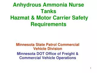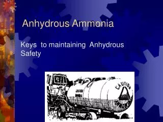
Anhydrous Ammonia
Anhydrous Ammonia. Storage and Handling. Original Power Point Created by Brandon Ritter Modified by Georgia Agricultural Education Curriculum Office June 2002. Definitions.


Anhydrous Ammonia
E N D
Presentation Transcript
Anhydrous Ammonia Storage and Handling Original Power Point Created by Brandon Ritter Modified by Georgia Agricultural Education Curriculum Office June 2002
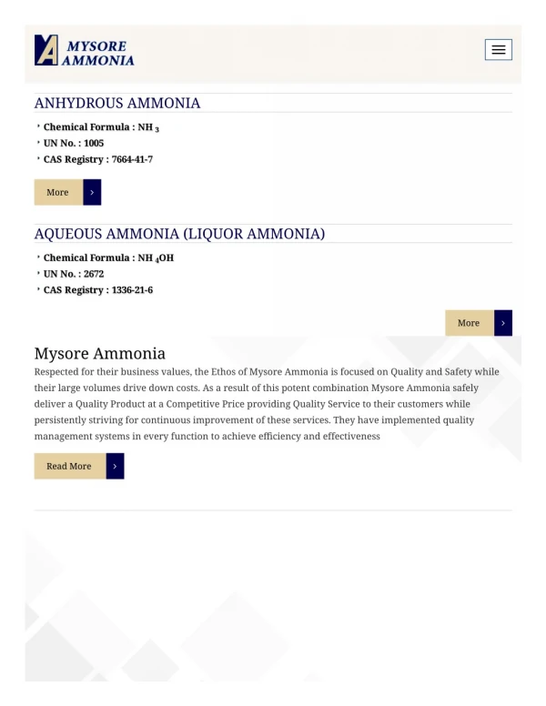
Definitions • Capacity is the total volume of the container in standard U.S. gallons. A cylinder is a container of 1,000 pounds of water capacity or less constructed in accordance with Department of Transportation specifications. • Design pressure is identical to the term "Maximum Allowable Working Pressure." • A farm vehicle (implement of husbandry) is a vehicle for use on a farm on which is mounted a container of not over 1,200 gallons water capacity. • Anhydrous ammonia is considered a gas in both its gaseous and liquefied state.
These regulations apply to containers of 1,200 gallons capacity or less and pertinent equipment mounted on farm vehicles (implements of husbandry) and used other than for the application of ammonia to the soil.
Design Pressure and Classification of Containers • The minimum design pressure for containers must be 250 p.s.i.g., and the shell or head thickness must be not less than three-sixteenths of an inch.
Mounting Containers • A suitable "stop" or "stops" must be mounted on the vehicle or on the container in such a way that the container may not be dislodged from its mounting due to the vehicle coming to a sudden stop. • Back slippage must also be prevented by proper methods. • Suitable "hold down" device must be provided which will anchor the container to the vehicle at one or more places on each side of the container
When mounted on four-wheel trailers, care must be taken to insure that the weight is distributed evenly over both axles. • When the cradle and the tank are not welded together, suitable material must be used between them to eliminate metal-to-metal friction.
Container Appurtenances • Containers must be equipped with a fixed liquid-level gage, and all those with a capacity exceeding 250 gallons must be equipped with a pressure gage having a dial graduated from 0-400 p.s.i.
The filling connection must be fitted with: • a combination back-pressure check valve and excess-flow valve, • one double or two single back-pressure check valves, or • a positive shutoff valve in conjunction with either an internal back-pressure check valve or an internal excess flow valve.
All containers with a capacity exceeding 250 gallons must be equipped for spray loading or with an approved vapor return valve. • All vapor and liquid connections except safety-relief valves (and pressure gage connections on container openings not larger than No. 54 drill size) must be equipped with approved excess-flow valves or may be fitted with quick-closing internal valves which, except during operating periods, must remain closed.
Fittings must be adequately protected from damage by a metal box or cylinder with open top securely fastened to the container or by rigid guards, well braced, welded to the container on both sides of the fittings or by a metal dome. If a metal dome is used, the relief valve must be properly vented through the dome. • If a liquid withdrawal line is installed in the bottom of a container, the connections, including hose, must not be lower than the lowest horizontal edge of the vehicle axle. Provision must be made to secure both ends of the hose while in transit.
Marking the Container • There must appear on each side and on the rear end of the container in letters at least four inches high, the words "Caution--Ammonia," or the container must be marked in accordance with DOT regulations.
Farm Vehicles • Farm vehicles must conform with any existing state regulations and must carry a can containing five gallons or more of water. • All trailers must be securely attached to the vehicle drawing them by means of drawbars supplemented by suitable safety chains. • Trailer must be constructed so that it will follow substantially in the path of the towing vehicle and will not whip or swerve dangerously from side to side.
These regulations apply to systems utilizing containers of 250 gallons capacity or less which are mounted on farm vehicles (implement of husbandry) and used for the application of ammonia to the soil. Where larger containers are used, they must comply with the requirements in the section Mounted Systems for the Storage and Transport of Ammonia.
Design Pressure and Classification of Containers • The minimum design pressure for containers must be 250 p.s.i.g., and the shell or head thickness must not be less than three-sixteenths inch.
Mounting of Containers • All containers and flow-control devices must be securely mounted.
Container Valves and Accessories • Each container must have a fixed liquid-level gage. The filling connection must be fitted with: • a combination back-pressure check valve and an excess-flow valve, • one double or two single back-pressure check valves, or • a positive shutoff valve in conjunction with an internal back-pressure check valve or an internal excess-flow valve. • The applicator tank may be filled by venting to open air provided the bleeder valve orifice does not exceed seven-sixteenths inch in diameter.
Regulation equipment may be connected directly to the tank coupling or flange, in which case a flexible connection must be used between such regulating equipment and the remainder of the liquid withdrawal system. Regulating equipment not so installed must be flexibly connected to the container shutoff valve. • No excess flow valve is required in the liquid withdrawal line provided the controlling orifice between the contents of the container and the outlet of the shutoff valve does not exceed seven-sixteenths inch in diameter.