Download
1 / 12
120 likes | 272 Vues
A Timed Automata Model of a Multilevel Converter. Mentee – Ted Hong Mentor – Taylor Johnson. Multilevel converters DC-to-AC: requires many DC sources and sums them to output a time-varying wave

E N D
A Timed Automata Model of a Multilevel Converter Mentee – Ted Hong Mentor – Taylor Johnson
Multilevel converters DC-to-AC: requires many DC sources and sums them to output a time-varying wave Ideal interface between a utility and renewable energy sources such as photovoltaics or fuel cells Simple and modular structure High efficiency (98%), less energy loss Claim: a timed automata model can be an accurate representation of multilevel converters Motivation and Problem
Multilevel Converter: DC to AC Switching Supply L. M. Tolbert, F. Z. Peng and T. G. Habetler, “Multilevel Converters for Large Electric Drives,” IEEE Transactions on Industry Applications, Vol.35, No. 1, 1999, pp. 36-44. doi:10.1109/28.740843
Model in Simulink 1) Generated by pulse signal generator: resulting waveform is a rectangle function with duty cycle depending on delay input 2) Then sum voltages
Simulink Simulation 11-Level Converter from 5 DC sources at 5V each (+/-5V from H-bridge) Conducting angle set to minimize the total harmonic distortion from a sine wave
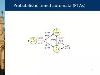
Model in UPPAL • Model checker for timed automata • Finite state machines + simple differential equations, dx/dt = 1 • Integrate: x = t • Model: clock for each level of the multilevel converter, only need to keep track of duty cycle • Can automatically verify various properties (model check) • Range of output
UPPAL Simulation 11-Level Converter from 5 DC sources at 1V each (+/-1V from H-bridge) Conducting angle set to minimize the total harmonic distortion from a sine wave
Acknowledgments My Mentor, Taylor Johnson The P.U.R.E Committee
H bridge—basic element • Simple Structure – fours switches • Each voltage level, with different duty cycle or conducting angles so that total harmonic distortion is minimized
How does it work? One multilevel converter incorporated with cascaded single phase H bridges with separate DC sources, for instance provided by a solar cell Structure—connected in series One H bridge L. M. Tolbert, F. Z. Peng and T. G. Habetler, “Multilevel Converters for Large Electric Drives,” IEEE Transactions on Industry Applications, Vol.35, No. 1, 1999, pp. 36-44. doi:10.1109/28.740843