Bluetooth
Bluetooth. Owen Garmire and Seila Kheang CSE 466 Fall 2001 http://www.cs.washington.edu/homes/seila/bluetooth.ppt. Bluetooth Overview. Wireless technology for short-range voice and data communication Low-cost and low-power


Bluetooth
E N D
Presentation Transcript
Bluetooth Owen Garmire and Seila Kheang CSE 466 Fall 2001 http://www.cs.washington.edu/homes/seila/bluetooth.ppt
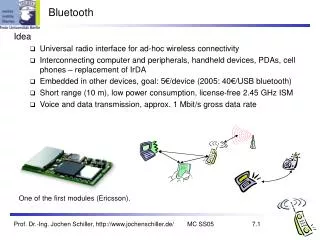
Bluetooth Overview • Wireless technology for short-range voice and data communication • Low-cost and low-power • Provides a communication platform between a wide range of “smart” devices • Not limited to “line of sight” communication
Digital Camera Computer Scanner Inkjet Printer PDA Cell Phone Home Audio System Cordless Phone Base Station Motivation
Bluetooth Applications • Automatic synchronization between mobile and stationary devices • Connecting mobile users to the internet using bluetooth-enabled wire-bound connection ports • Dynamic creation of private networks
Synchronization • Keep data on different devices synchronized without using a cable • Example: • Walk into office and have your PDA synch with your laptop on your desk without even taking your PDA out of your briefcase
Connecting to Internet • Being able to gain access to the Internet by using “Bluetooth access points” • Access point is used as a gateway to the internet • Both the access point and the device are Bluetooth-enabled • An example of Service Discovery Protocol • Access point provides a service to the device
Ad Hoc Networks • Up to 8 devices can be actively connected in master/slave configuration • Piconets can be combined to form scatternets providing unlimited device connectivity
Bluetooth Radio • Uses 2.4 GHz ISM band spread spectrum radio (2400 – 2483.5 MHz) • Advantages • Free • Open to everyone worldwide • Disadvantages • Can be noisy (microwaves, cordless phones, garage door openers)
Frequency Hopping • In order to mitigate interference, Bluetooth implements frequency hopping • 1600 hops per second through 79 1MHz channels • Spreads Bluetooth traffic over the entire ISM band • All slaves in piconet follow the master for frequency hop sequence
Frequency Hopping (cont.) • Hops every packet • Packets can be 1, 3, or 5 slots long (a slot is 625µs) • Packets are pretty short
Baseband Layer • Provides in-order delivery of byte streams • Handles Frequency Hop Sequences for Synchronization and Transmission • Establishes Links • Synchronous Connection Oriented (SCO) • Asynchronous Connection-Less (ACL) • Provides functionality to determine nearby Bluetooth devices
Connection (Inquiry and Paging) Link controller states during connection process
Bluetooth: Hello, Anyone Around? • Inquiry Procedure • Sends out an inquire, which is a request for nearby devices (within 10 meters) • Devices that allow themselves to be discoverable issue an inquiry response • Can take up to 10.24 seconds, after which the inquiring device should know everyone within 10 meters of itself
Note that a device can be “Undiscoverable” H Device Discovery Illustrated D F N H G M A P B O E K J L Q I C 10 meters After inquiry procedure, A knows about others within range
Issues with Inquire Messages • Are the inquirer transmitting and the receiver listening on the same frequency? • Since they are not yet connected, they are on totally different hop sequences, and most likely on different channels • If they are on the same frequency, what if they are on a noisy channel? • Bluetooth provides the capability for receivers to issue multiple inquiry responses
Main Idea Behind Inquire • Inquiring device sends out an inquire on 16 different frequencies (16 channel train) • Receiver (device in standby mode), performs an inquire scan long enough for an inquiring device to send the inquire on 16 frequencies • Receiver does an inquire scan frequent enough so that it is guaranteed to wake up during a 16 channel train
The Numbers Behind Inquire • Each full scan of a 16 channel train takes about 1.28 seconds • 16 channels * 625us * 128 trains = 1.28 seconds • One full 16 channel train takes 10ms. • Receiver enters inquiry scan state at least once every 1.28 seconds, and stays in that state for 10ms.
What about noise? • Devices always reply to received inquiry messages with an inquiry response • An inquirer is allowed to received multiple responses from one device • In order to account for the fact that channels can be noisy and transmissions can get lost, the 128 train scan is repeated up to 4 times for each train (10.24 seconds) • Designed to successfully communicate at least once with all devices within range
Inquiry • Uses 32 inquire channels to send out inquiry messages • Send out inquiry on 32 channels, broken up into 2 inquiry hop trains (16 different channels to transmit packets) • Intended to catch a device in inquiry scan mode on one of the 32 inquire channels
Inquiry Scan • A device periodically listens for inquiry packets at a single frequency – chosen out of 16 frequencies • Inquiry hop sequence depends on device address • Stays in the state long enough for a inquiring device to cover 16 frequencies • Will re-enter inquiry scan state even after responding to an inquire
Inquiry Response • When radio receives inquire, it will wait between 0 and .32 seconds before sending an FHS packet as a response • This is done to avoid collision with another radio that also wants to send an FHS packet • FHS Packet contains: • Device ID • Clock • After inquiring radio is done with inquiring procedure, it knows all of the radios (that are discoverable) within range
Paging: Will you connect to me? • Very similar to inquire • Still have not synchronized clocks or frequencies • Establishes actual Piconet connection with a device that it knows about • Connection process involves a 6 steps of communication between the the master and the slave
Paging Illustrated D F N H G M A A A B P B O E K J L Q I C 10 meters
Step 1: The Page Command • Device broadcasts a page message out to the device that it wants to set up a connection with • Does this in a similar manner as inquire messages (on 2 frequency trains of 16 frequencies each) • Once the device receives a page response, it will stop paging and move on to step 2
Paging: Steps 2 & 3 • Step 2: In the page response, an acknowledgement is sent back to the master containing the slave ID • Step 3: In the master response, the frequency hopping generator is stopped and the master issues an FHS packet to the slave
Paging: Step 4 • The slave issues a final slave response transmission that is aligned to the slave’s native clock • Using the data from the FHS packet, the slave calculates adopts the master’s frequency hopping pattern and synchronizes to its clock
Paging: Step 5 • When the master receives the packet, it jumps back to its frequency hopping pattern and assigns the slave an Active Member Address (AMA) for the piconet • Master sends out a poll packet to ensure that the slave is on its frequency hopping pattern
Paging: Step 6 • Once the slave receives the poll packet, the slave replies with any kind of packet to ensure that it is on the right channel • The acknowledgement must be received by the Master within the timeout period • At the conclusion of step 6, a new synchronized connection is established between the master and the slave
Link Manager • Performs all link creation, management, and termination operations • Responsible for all the physical link resources in the system • Handles the control and negotiation of packet sizes used when transmitting data • Controls Operation Modes for devices in a piconet • Sets up, terminates, and manages baseband connections between devices • Establishes different types of links dependent on requests from the L2CAP layer • Synchronous Connection-Oriented (SCO) • Asynchronous Connection-Less (ACL)
Asynchronous Connection-Less (ACL) • Designed for data traffic • Packet switched connection where data is exchanged sporadically as and when data is available from higher up the stack • Data integrity is checked through error checking and retransmission • One ACL link between a master and a slave
Synchronous Connection Oriented (SCO) • Intended for use with time-bounded information such as audio or video • Provides a circuit-switched connection where data is regularly exchanged • Retransmission is not necessary, since data is real-time • Up to 3 SCO links per piconet
Establishing Piconets • Whenever there is a connection between two Bluetooth devices, a piconet is formed • Always 1 master and up to 7 active slaves • Any Bluetooth device can be either a master or a slave • Can be a master of one piconet and a slave of another piconet at the same time (scatternet) • All devices have the same timing and frequency hopping sequence
Scatternets • Formed by two or more Piconets • Master of one piconet can participate as a slave in another connected piconet • No time or frequency synchronization between piconets
Link Manager Operation • Devices operate in standby mode by default until they become connected to a piconet • 4 Connection Modes • Active • Hold • Park • Sniff • Modes allow devices to adjust power consumption, performance, and the number/role of participants in a piconet
Active Mode • Limited to 7 Active slaves for each master • Three bit address (AM_ADDR) given to each active slave • Unit actively participates on channel • Can receive communications in any given frame • Active slaves are polled by master for transmissions • Unit operates on high-power
Hold Mode • Frees slave to • Attend another Piconet • Perform scanning, paging, or inquiry operations • Move into low-power sleep • Unit keeps active member address • Unit does not support ACL packets on the channel but may support SCO packets • Master and slave agree on a one time hold duration after which the slave revives and synchronizes with channel traffic • Unit operates on low-power
Sniff Mode • Very similar to hold mode • Slave is freed for reoccurring fixed time intervals • Master can only communicate during arranged “sniff” time slots
Park Mode • Parked unit gives up active member address and is assigned • 8 bit Parked member address (PM_ADDR) – allows master to unpark slave • 8 bit Access request address (AR_ADDR) – allows slave to ask master to unpark it • Unit stays synchronized to channel • Operates in very low-power sleep
Park Mode (cont.) • Provides the ability to connect more than 7 devices to a master (8 bit PM_ADDR allows 255 parked devices) • Active and Parked slaves can be switched in and out to allow many connections to a single piconet
Park Mode (cont.) • Master establishes a beacon channel and beacon interval when a slave is parked • Parked slave wakes up at regular beacon interval to • Maintain synchronization • Listen for “broadcast” messages (packets with all zero AM_ADDR) • Potentially make access request to master through (AR_ADDR)
Park Mode (cont.) • Beacon slots must have at least “null” master-to-slave traffic • Master-to-slave transmissions may extend over multiple beacon slots
Security • Link manager provides mechanism used by devices at either end of a link for • Negotiating encryption mode • Coordinating encryption keys • Baseband handles encryption and key generation
Host Controller Interface (HCI) • Most Bluetooth systems consist of two processors: • The higher layers of the protocol stack (L2CAP, SDP, RFCOMM) are run on the host device’s processor • The lower layers of the protocol stack (Baseband and radio) are run on specific Bluetooth hardware • HCI provides an interface between the higher and the lower layers of the protocol stack
HCI Flow Control • Main function of the Host Controller Interface • Many times higher layer protocols have data rates much larger than data rate across Bluetooth radio and air interfaces • Also need to handle the reverse situation when the host cannot accept data as fast as the Bluetooth module can send it
Two Pieces of HCI • Host controller resides on Bluetooth hardware accepting communications over the physical bus (radio and air) • HCI Driver resides on the host accepting communications from higher layer protocols
The basic structure showing how the host controller layers are fitted into the protocol stack