Multiple-output, Variable-output DC Power Supply May03-22
Multiple-output, Variable-output DC Power Supply May03-22. Team Members: Erik Johnson Joel Jorgensen Peter Holm Philip Schulz Clients – Prof. Patterson, Prof. Lamont Faculty Advisor – Dr. Allan Potter April 30 th , 2003. Presentation Overview. Problem statement and solutions

Multiple-output, Variable-output DC Power Supply May03-22
E N D
Presentation Transcript
Multiple-output, Variable-output DC Power SupplyMay03-22 Team Members: Erik Johnson Joel Jorgensen Peter Holm Philip Schulz Clients – Prof. Patterson, Prof. Lamont Faculty Advisor – Dr. Allan Potter April 30th, 2003
Presentation Overview • Problem statement and solutions • Summary of activities • Resource requirements • Summary of progress • Questions
General Problem Statement • Develop a power supply with the following voltages: +1.5V, 3.0V, +3.2V, +4.5V, 5.0V, +6.0V, +7.5V, +9.0V, 12.0V, +15.0V, +18.0V, +24.0V • Output 2 + voltage outputs and 2 + voltage outputs simultaneously • Produce for a low cost (~$150) • Allow a maximum current of 1A through each set of terminals
Solution Approach • Develop general design • Simulate and test on CAD program • Order parts • Assemble • Test • Modify and re-test if necessary
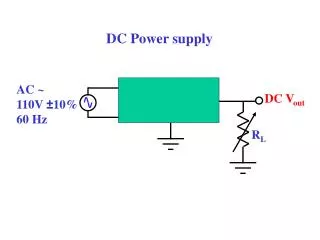
Operating Environment • Standard laboratory conditions • Indoors • Approximately 24 degrees Celsius • Standard 120V, 60 Hz wall output
End Users and Uses • Users • Research and design students • Faculty • Uses • Power and test design projects • Produce a small current at many voltages • Provide several voltages simultaneously
Assumptions and Limitations • Assumptions • All four outputs will be used simultaneously • Power supply will be used indoors at room temp • Power supply will be powered by 120V, 60 Hz • Limitations • Output current limited to 1A max per output • Total cost must be below $150 • Input must be 120V at 60 Hz
End Product Description • 4 selectable output voltage terminal sets • Maximum current of 1A per output • Output voltage selected by rotary knobs • Digital readout of voltage, current and wattage • Fuses for power supply protection
Present Accomplishments • Schematic simulated and successful • Successfully implemented transformer and bridge rectifiers on circuit board • Successfully implemented +/- voltages on circuit board • Examined methods of implementing positive only voltages
Approaches to the Design • Recycle/modify/incorporate existing insufficient power supplies • Create and design an original power supply • Use store-bought voltage converters • Design and create voltage converters • Flyback converter • Buck converters • LM317T/LM337T voltage regulators
Project Definition Activities • The power supply specs were expanded from the original to include the following: • +3.2V, +7.5V, +15V, and +18V • 2 + voltage outputs and 2 + voltage outputs • Ammeter and voltmeter
Research Activities • The need for more voltage outputs was researched. • It was found that the additional voltages of +3.2V, +7.5V, +15V, and +18V would be useful for small home electronics • Also researched various power supply designs for ideas to implement in the final product.
LM317T/LM337T Voltage Regulators • Adjustable output down to +1.2v • Adjustable current limiting feature • Line regulation typically .01%/V • Load regulation typically .1% • 80 dB ripple rejection
TL494 PWM Control Circuit • Up to 200 kHz oscillator frequency • Feedback allows voltage and current regulation
Design Activities • Different implementation schematics tested • Because the LM317T/LM337T voltage regulators are not in the Workbench/Pspice libraries, the circuits were physically tested
Team Members Paper Work Research Design Construction Totals Est. Act. Est Act. Est. Act. Est. Act. Est. Act. Erik Johnson 8 10 21 14 32 25 12 13 73 58 Joel Jorgensen 5 27 25 13 34 26 13 14 77 76 Peter Holm 9 25 15 7 25 22 14 8 63 58 Philip Schulz 7 10 18 8 28 27 12 12 65 53 Totals 27 72 79 42 119 100 51 47 278 265 Personnel Effort Budget
Item Original Estimated Cost Cost to Date Poster $50.00 $50.00 Case $14.99 $0.00 Transformers $35.53 $21.94 Resistors/capacitors/diodes $26.80 $21.18 Cooling fan $9.99 $8.99 Switches, dials, and terminals $25.00 $6.21 Meters ($10.25 each) $30.75 $0.00 Variable voltage regulator $4.00 $3.90 Total $197.07 $112.22 Financial Budget
Project Evaluation • Done on a scale of: incomplete = 0%, to complete = 100% • Milestones: • Overall Status: Prototype
Commercialization • Estimated cost to produce: $100 - $200 • Estimated sales price: $400 - $1000 • It is anticipated that this product would have a very large market • Versatile • Financially viable
Recommendations forAdditional Work • Finish original implementation • Develop a commercial version • Add power factor correction • Make each set of terminals fully isolated • Make current limitation adjustable
Lessons Learned • What worked • Team worked well at brainstorming, designing • Advisor was helpful when we got stuck • Regular, scheduled meeting • What did not work • Collaborating on reports and poster • Weekly status reports • Ordering parts • Gaining the necessary knowledge • Advisor absence for extended period of time
Lessons Learned (cont) • Technical knowledge gained • How power supplies work • How DC-DC converters work • How transformers work • How to use Workbench • Things to do differently • Put more time into research early on
Risks and Risk Management • Illness • Follow good health practices • Take on some of the sick member’s workload among the other members • Accidents such as electrocution or fire • Follow high voltage safety procedures when assembling • Cut power, use First Aid, call 911, put out fire • Losing a team member • Be such a good team that nobody wants to leave • Divide the work among the remaining members, seek assistance from colleagues
Summary • Problem: Replace the current power supplies with a single versatile tool • Approach: Consider several different alternatives by which multiple voltages can be provided simultaneously by a single power supply • Solution: Provide two plus/ground terminals and two plus/minus/ground terminals whose voltage can be set independently of the others. Also provide meters to display the voltage, current, and wattage of the selected set of terminals