Download
1 / 3
30 likes | 133 Vues
Solve problems on converting codes, designing counters, Mealy systems, and alarm systems in digital circuits. Includes state diagrams, ASM charts, and detailed systems designs.

E N D
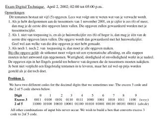
Exam Digital Technique. April 2, 2002; 02:00 tot 05:00 p.m.. Problem 1. We have two different codes for the decimal digits that we sometimes use: The excess 3 code and the 2 of 5 code shown below. Digit 0 1 2 3 4 5 6 7 8 9 Excess 3 0011 0100 0101 0110 0111 1000 1001 1010 1011 1100 (wxyz) 2 of 5 11000 10100 10010 10001 01100 01010 01001 00110 00101 00011 (abcde) All other combinations of input bits never occur. We wish to build a box that converts excess 3 code to 2of 5 code.
Implement this converter into a minimal PLA. Problem 2. Design a synchronous counter that goes through the sequence 2 6 1 7 5 and repeat, using D flip flops. Show a state diagram indicating what happens if it initially is in one of the forbidden states (0, 3, 4) for your design. Problem 3. Design a Mealy system whose output is 1 if and only if there have been exactly two 1’s followed by a 0 and then a 1, a. assuming overlapping is allowed, b. assuming overlapping is not allowed. Problem 4. You will design a rudimentary alarm system. The first part of the system includes a flip flop A that is 1 if the alarm is set and 0 if it is not, and a keypad with 10 keys and 4 output lines. It produces all 1’s (hexadecimal F) if no key is pushed, and 0000 to 1001 if one of the keys 0 to 9 is pushed. (You may assume that two keys are never pushed at the same time, and that the keypad never produces one of the five other combinations). To set or clear the alarm, a 3-digit combination must be entered. Hidden away in the control box is a set of three 10-position switches (that contain the 3-digit alarm code). The switches each produce 4-bit number, R[1:4], S[1:4], and T[1:4]. If one pushes a keys to enter the alarm code,
Specify an instruction format for the microprogrammed computer that performs the following two operations (DR, SA and SB are the destination, source A, and source B registers, respectively). R[DR] R[SB] + M[SA] and M[SA] M[SA] + R[SA] the first digit will appear on the keypad output for several clock periods, followed by a hexadecimal F (indicating that no key is pushed) for several more clock periods, followed by the second digit, etc. You must design a system that watches the keypad and, if the right code is received, complement A. Assume that there is at least one clock period when no key is pushed between digits. However, if another key is not pushed within 100 clocks, then the system goes back to looking for the first digit. The second part of the system is used to sound the alarm. There is an input signal D indicating that a door is open (1) or closed (0), and an output N indicating that the alarm is sounded (1) or not (0). (Of course, A is also an input to this part of the system). When the alarm is first set, the door must be closed within 1000 clock pulses or the alarm will sound. Also, if the alarm has been set for more than 1000 clock cycles and the door is open, then the alarm will sound if it is not reset within 1000 clock periods. Design both parts of this system. Available components are negative-edge triggered JF flip flops, synchronous 4-bit binary or decimal counters, and whatever gates that are needed. Give an ASM (Algorithmic state machine) for the first part, and a block diagram for the complete system. Give a systematic derivation of your results. Problem 5. Find the ASM chart to implementing the instruction you have found, assuming that the opcode is 0000111. List the sequence of microoperations for executing this instructions, including the handling of the CAR values (Control Address Register).