Download

1 / 44
440 likes | 495 Vues
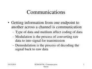
Communications Equipment. Communication Equipments: Equipments that are, Not a direct part of the network (like node, client, terminal, server etc.) but, Indirectly they are a part of network and, Are required for communication between the source and the destination. Communications Equipment.

E N D
Communications Equipment Communication Equipments: Equipments that are, Not a direct part of the network (like node, client, terminal, server etc.) but, Indirectly they are a part of network and, Are required for communication between the source and the destination.
Communications Equipment Multiplexer MUX Demultiplexer DEMUX
Communications Equipment Multiplexer (Mux) / De-multiplexer (Demux): Multiplexer: Device that, Receives the input signals from several devices, Combines them into a single stream of data, and then Transmits the data over a single communications line. Process of combining various signals into one is called: Multiplexing De-multiplexer: Device that, Recovers the input signal and divides them as, Separate signals again. Process of separating the signals from a single signal is called: De-multiplexing Most multiplexers today include, Both multiplexing and de-multiplexing functionality.
Multiplexer / Demultiplexer Advantages: Increases the efficiency of communications by reducing the, Cost of communications by, Combining the data of various communication lines onto a single communication line. If each client had its own dedicated line, The line would be idle most of the time. The process of combining the links onto 1 transmission line is, Transparent and hence, The network behaves as if each connection was occurring over a separate physical line. Organizations need to lease (rent) only, A single long-distance line to, Transmit many voice and data signals between two offices in different cities.
Multiplexer / Demultiplexer Multipoint line v/s Multiplexed line: Multipoint line: Physically a single line and logically, Also a single communication channel. Allows only, 1 client to transmit over the line at a time. Requires only, 1 port / interface for connection. Requires algorithm to avoid congestion. Multiplexed line: Physically a single line is logically, Divided into multiple communication channels. Allows, Many clients to transmit at the same time. Requires, Many ports / intefaces for connection because, The multiplexed line needs to be demultiplexed at some point of time into separate lines. Algorithm to avoid congestion is not required.
Communications Equipment Multiplexing: Depending on how the signals are multiplexed (joined/combined) together, classification is: Guided Media/Signal: Frequency Division Multiplexing (FDM) Time Division Multiplexing (TDM) Statistical Time Division Multiplexing (STDM) Wave Division Multiplexing (WDM) Unguided Media/Signal: Frequency Division Multiple Access (FDMA) Time Division Multiple Access (TDMA) Used in GSM cellular phones. Code Division Multiple Access (CDMA) Used in CDMA cellular phones.
4,000 Hz Guardband (4,000 – 3,300) = 700 Hz 3,300 Hz Data (3,300 – 300) = 3,000 Hz 300 Hz Guardband (300 - 0) = 300 Hz 0 Hz Frequency Division Multiplexing (FDM) Multiplexing 0 to 4000 Hz / 0 to 4 KHz (4000 Hz) Interference? No. Because of Guardbands. 12000 to 16000 Hz / 12 to 16 KHz (4000 Hz) 8000 to 12000 Hz / 8 to 12 KHz (4000 Hz) 4000 to 8000 Hz / 4 to 8 KHz (4000 Hz) 0 to 4000 Hz / 0 to 4 KHz (4000 Hz) Bandwidth 0 to 4000 Hz / 0 to 4 KHz (4000 Hz) 16000 Hz / 16 KHz
Multiplexing Frequency Division Multiplexing (FDM): The bandwidth of the entire communications line is, Logically divided into, Narrower (thin) bandwidths / channels so that, Each client on the line can use one frequency range to transmit data. The gaps that occur between the frequency ranges are available for, Guardbands which are, Frequency ranges used to separate the individual signals so that, They do not interfere with each other. Example: FDM might assign following frequency channels to each 4 KHz telephone line that is connected: 1st channel: 0 KHz to 4 KHz 2nd channel: 4 KHz to 8 KHz 3rd channel: 8 KHz to 12 KHz and so on. Guardbands in each 4 KHz channel prevent, The voice or data signals from interfering with one another.
Multiplexing Frequency Division Multiplexing (FDM): Types: Group: If 12 of these 4 KHz lines are combined onto a, 12x4 = 48 KHz line. SuperGroup: If 60 such lines are combined onto a, 60x4 = 240 KHz line. MasterGroup: If 600 such lines are combined onto a, 600x4 = 2400 KHz (2.4 MHz) line. JumboGroup: If 3,600 such lines are combined onto a, 3600x4 = 14400 KHz (14.4 MHz) line
Multiplexing Frequency Division Multiplexing (FDM): Disadvantages: If the client does not have any data to transmit, That logical part of transmission line remains idle. Some part of bandwidth is also wasted in, Trying to protect the signals from interference, i.e. Guardbands. Use: For analog cable television transmission.
4,000 Hz Guardband (4,000 – 3,300) = 700 Hz 3,300 Hz Data (3,300 – 300) = 3,000 Hz 300 Hz Guardband (300 - 0) = 300 Hz 0 Hz Time Division Multiplexing (TDM) Multiplexing 0 to 4000 Hz / 0 to 4 KHz (4000 Hz) C4 C3 C1 C2 C3 C4 C1 C2 C2 Bandwidth 4000 Hz / 4 KHz C1 or 0 to 4000 Hz / 0 to 4 KHz (4000 Hz) 3000 Hz / 3 KHz
Multiplexing Time Division Multiplexing (TDM): TDM divides the transmission time slot into, Small Time Segments / Time Slices instead of, Using different frequency ranges to transmit data as in FDM. Each client is assigned a, Fixed time slot in, Rotation, during which it can transmit data and, During that slot, The client is given the full transmission capacity/bandwidth of the line. A major difference between TDM and FDM in how the signals are separated is, FDM uses, Frequency guardbands to separate signals whereas, TDM uses, Time to separate the signals.
Multiplexing Time Division Multiplexing (TDM): Disadvantage: If the client does not have any data to transmit during its fixed time slot, The transmission line remains idle during that time and, No other client can use that time slot.
4,000 Hz Guardband (4,000 – 3,300) = 700 Hz 3,300 Hz Data (3,300 – 300) = 3,000 Hz 300 Hz Guardband (300 - 0) = 300 Hz 0 Hz Statistical Time Division Multiplexing (STDM) Multiplexing 0 to 4000 Hz / 0 to 4 KHz (4000 Hz) C4 C3 C2 C1 C2 C3 C3 C2 Bandwidth 4000 Hz / 4 KHz C1 or 0 to 4000 Hz / 0 to 4 KHz (4000 Hz) 3000 Hz / 3 KHz
Multiplexing Statistical Time Division Multiplexing (STDM): Developed to overcome the problem of, Idle time on the transmission line and make better use of bandwidth. Unlike TDM, in STDM, Time slots are assigned to the clients, Dynamically and not Statically (Fixed). So if a client does not have data to transmit, STDM will not leave an open time slot on the transmission line. In most cases, this results in, Less idle time on the transmission line and improves efficiency. Major difference between TDM and STDM is: TDM is driven by time whereas, STDM is driven by data.
Multiplexing Statistical Time Division Multiplexing (STDM): Problem / Challenge / Disadvantage: If all the clients want to send data at the same time then, STDM has/uses special feature called, Buffers to, Store the excess data in memory until, Bandwidth is available on the line for each transmission. STDM is more costly than TDM because, It has more advanced functions than TDM.
Multiplexing Wavelength Division Multiplexing (WDM): Similar to FDM (Frequency Division Multiplexing) done on, Fiber-optic cables and so, WDM is the optical equivalent of FDM. Each signal is assigned to, A particular wavelength (i.e. particular frequency) on optical fiber communications line which enables, Bi-directional communication over 1 optical fiber and, Increase in the capacity/bandwidth as well. Different frequencies (or wavelengths), Allow, Many different transmissions to exist on the same optical fiber at the same time. Prevent, Individual signals from interfering with each other. Advanced form of WDM has also been invented called: DWDM: Dense Wavelength Division Multiplexing
Multiplexing Wavelength Division Multiplexing (WDM): BOTTLENECK Problem: Internet infrastructure uses WDM to give speeds of, MegaBytes per second (MBps) and, GigaBytes per per second (GBps) yet, Internet users get the speeds only in, KiloBits per second (Kbps). Reason: Ultimately optical fibers are always connected to, Networks that use copper wire. Copper networks can only carry, Electrical signals and not Light signals. So some kind of conversion needs to be done at both the ends of transmission (Light to Electricity & vice-versa) and, These conversions take time and slow down end-to-end transmission. Moreover, customer’s home and the local telephone company end office are connected by, Slow-speed analog line.
Multiplexing Multiplexing: Multiplexing techniques discussed so far such as, ‘FDM’, ‘TDM’, ‘STDM’ and ‘WDM’ apply to, Guided media such as, Copper Wire (Twisted Pair / Coaxial Cable) or Fiber Optic Cable. To share bandwidth, wireless (unguided) communications also make use of, Multiplexing systems such as, FDMA: Frequency Division Multiple Access. TDMA: Time Division Multiple Access. ETDMA: Enhanced Time Division Multiple Access. CDMA: Code Division Multiple Access.
Multiplexing Multiplexing for Unguided/Wireless Media: Consider an room where people wish to talk to each other simultaneously: Speak at different pitches (frequencies). Frequency Division Multiple Access. Take turns speaking. Time Division Multiple Access. Speak in different languages altogether at any time and at any pitch. Code Division Multiple Access.
Multiplexing Frequency Division Multiple Access (FDMA): Similar to FDM (Frequency Division Multiplexing) of Guided Media. Entire bandwidth (frequency range) is divided into, Smaller frequencies which can be, Allocated to different callers/customers. At a time, in one cell, a single frequency can be used by: Only one caller and, No other caller can use that same frequency until, The first call is terminated. Used in: Analog cellular communication systems such as: AMPS (Advanced Mobile Phone Service) Disadvantages: One frequency can be used by only a single caller/customer at a time in a cell. Bandwidth remains idle if customer is not transmitting the data.
Multiplexing Time Division Multiple Access (TDMA): Similar to TDM (Time Division Multiplexing) of Guided Media. Mainly developed to, Further increase the efficiency of digital cellular systems. With TDMA, The frequency is divided into time slots which allows, Multiple users to access the same frequency simultaneously. In a given cell, the number of users who can share the same frequency is: 3 (Three) Used in: GSM (Global System for Mobile Communications) communications to handle voice and data transmissions. Disadvantages: Bandwidth remains idle if customer is not transmitting the data.
Multiplexing Enhanced Time Division Multiple Access (ETDMA): In TDMA, If a user makes a call, A fixed time slot is allocated to that user, Whether or not anyone is speaking at a particular time. Hence, Empty time slots exist when user, Is not transmitting any data. To overcome this inefficiency, Enhanced Time Division Multiple Access (ETDMA) was developed. In ETDMA, Time slots are allocated to users dynamically only when, They are transmitting and not on a, Fixed basis. If no one is speaking during a certain time period, ETDMA allows that time slot to be used by another conversation and hence, A single conversation might occur over multiple frequencies.
Multiplexing Code Division Multiple Access (CDMA): Assigns each conversation a, Unique code. Both the entities, Mobile Telephone and Base Station use this code to, Identify signals that are part of that conversation. CDMA uses, Direct sequence spread spectrum (DSSS) technology which means that, Original signal is spread over several frequencies simultaneously. Used in: 3G wireless technology.
CDMA Advantages & Disadvantages of CDMA: Debatable Advantages of CDMA: Capacity of CDMA is greater than FDMA or TDMA. Superior call quality. Disadvantage of CDMA: Cost of the base station with its complex communications equipment is very high.
Inverse Multiplexer Multiplexer Configurations Inverse Multiplexing is also called Bonding.
Cascading Multiplexer Multiplexer Configurations
Interconnecting Devices Interconnecting Devices: Many devices have been developed to Interconnect devices and to, Connect networks together. Some of these devices could be: Hubs, Switches, Routers, Bridges.
Interconnecting Devices Hub Switch Router
Interconnecting Devices Hubs: Generally a Layer-1 (Physical Layer) device. It is a dumb device which, Cannot read the destination MAC address and hence, Forwards the packet to all connected devices and hence becomes, Inefficient in larger networks. Use: Generally used to connect small networks. With a hub, The network becomes a star topology.
Interconnecting Devices Switches: Generally a Layer-2 (Data Link Layer) device. It is an intelligent device which, Can read the destination MAC address and hence, Can forward the packet only to the destination and not all the connected devices which makes it, Efficient in larger networks. Use: Generally used to connect large networks.
Interconnecting Devices Routers: Generally a Layer-3 (Network/IP Layer) device. Main job is to, Route packets to other networks until, The packet reaches its destination. Normally used to connect, LAN to a WAN (such as Internet). 2 types of routing exist: Static Routing: Route/Path is manually hard-coded into the router. Dynamic Routing: Route/Path is dynamically determined by the router itself. Modern routers can also act as: Firewalls.
Interconnecting Devices Bridges: Bridge is an outdated device which was used to, Connect two local area networks. Could be considered as, Hub/Switch with only 2 ports. Originally it was used only, In environments in which the networks used the same protocol.
Bridge Interconnecting Devices
Other Equipments Other Equipments: Front-End Processors (FEP): Types: Non-programmable FEP. Programmable FEP. Controllers: Types: Remote Controllers. Local Controllers. Protocol Converters: If 2 or more devices use different protocols, then, Communications are established through the use of a protocol converter. It can be considered as an: Interpreter. Example: A PC that used the ASCII data code cannot directly communicate with an IBM computer that uses the EBCDIC data code. This can be achieved using Protocol Converter. Types: Hardware based Protocol Converter. Software based Protocol Converter.
Ancillary Equipments Ancillary Equipments: Diagnostic Equipment: Line Monitors: Used to monitor the actual data being transmitted over the line. Network Sniffer: Hardware and/or Software that monitors all network traffic. Breakout Box: Checks the voltage levels of a communications line to detect errors caused by fluctuation in voltages. Port Concentrators & Selectors: Patch Panel.
Patch Panel Ancillary Equipments