Chapter 23 CUTTING TOOL TECHNOLOGY
Chapter 23 CUTTING TOOL TECHNOLOGY. Tool Life Tool Materials Tool Geometry Cutting Fluids. Cutting Tool Technology . Two principal aspects: Tool material Tool geometry. Three Modes of Tool Failure. Fracture failure

Chapter 23 CUTTING TOOL TECHNOLOGY
E N D
Presentation Transcript
Chapter 23CUTTING TOOL TECHNOLOGY • Tool Life • Tool Materials • Tool Geometry • Cutting Fluids ISE 316 - Manufacturing Processes Engineering
Cutting Tool Technology Two principal aspects: • Tool material • Tool geometry ISE 316 - Manufacturing Processes Engineering
Three Modes of Tool Failure • Fracture failure • Cutting force becomes excessive and/or dynamic, leading to brittle fracture • Temperature failure • Cutting temperature is too high for the tool material • Gradual wear • Gradual wearing of the cutting tool ISE 316 - Manufacturing Processes Engineering
Preferred Mode of Tool Failure: Gradual Wear • Fracture and temperature failures are premature failures • Gradual wear is preferred because it leads to the longest possible use of the tool • Gradual wear occurs at two locations on a tool: • Crater wear – occurs on top rake face • Flank wear – occurs on flank (side of tool) ISE 316 - Manufacturing Processes Engineering
Figure 23.1 ‑ Diagram of worn cutting tool, showing the principal locations and types of wear that occur ISE 316 - Manufacturing Processes Engineering
Figure 23.2 ‑ • Crater wear, and • flank wear on a cemented carbide tool, as seen through a toolmaker's microscope (Courtesy Manufacturing Technology Laboratory, Lehigh University, photo by J. C. Keefe) ISE 316 - Manufacturing Processes Engineering
Figure 23.3 ‑ Tool wear as a function of cutting time Flank wear (FW) is used here as the measure of tool wear Crater wear follows a similar growth curve ISE 316 - Manufacturing Processes Engineering
Figure 23.4 ‑ Effect of cutting speed on tool flank wear (FW) for three cutting speeds, using a tool life criterion of 0.50 mm flankwear ISE 316 - Manufacturing Processes Engineering
Figure 23.5 ‑ Natural log‑log plot of cutting speed vs tool life ISE 316 - Manufacturing Processes Engineering
Taylor Tool Life Equation This relationship is credited to F. W. Taylor (~1900) • where v = cutting speed; T = tool life; and n and C are parameters that depend on feed, depth of cut, work material, tooling material, and the tool life criterion used • n is the slope of the plot • C is the intercept on the speed axis ISE 316 - Manufacturing Processes Engineering
Tool Life Criteria in Production • Complete failure of cutting edge • Visual inspection of flank wear (or crater wear) by the machine operator • Fingernail test across cutting edge • Changes in sound emitted from operation • Chips become ribbony, stringy, and difficult to dispose of • Degradation of surface finish • Increased power • Workpiece count • Cumulative cutting time ISE 316 - Manufacturing Processes Engineering
Tool Materials • Tool failure modes identify the important properties that a tool material should possess: • Toughness ‑ to avoid fracture failure • Hot hardness ‑ ability to retain hardness at high temperatures • Wear resistance ‑ hardness is the most important property to resist abrasive wear ISE 316 - Manufacturing Processes Engineering
Figure 23.6 ‑ Typical hot hardness relationships for selected tool materials. Plain carbon steel shows a rapid loss of hardness as temperature increases. High speed steel is substantially better, while cemented carbides and ceramics are significantly harder at elevated temperatures. ISE 316 - Manufacturing Processes Engineering
Typical Values of n and C in Taylor Tool Life Equation Tool materialnC (m/min)C (ft/min) High speed steel: Non-steel work 0.125 120 350 Steel work 0.125 70 200 Cemented carbide Non-steel work 0.25 900 2700 Steel work 0.25 500 1500 Ceramic Steel work 0.6 3000 10,000 ISE 316 - Manufacturing Processes Engineering
High Speed Steel (HSS) Highly alloyed tool steel capable of maintaining hardness at elevated temperatures better than high carbon and low alloy steels • One of the most important cutting tool materials • Especially suited to applications involving complicated tool geometries, such as drills, taps, milling cutters, and broaches • Two basic types (AISI) • Tungsten‑type, designated T‑ grades • Molybdenum‑type, designated M‑grades ISE 316 - Manufacturing Processes Engineering
High Speed Steel Composition • Typical alloying ingredients: • Tungsten and/or Molybdenum • Chromium and Vanadium • Carbon, of course • Cobalt in some grades • Typical composition: • Grade T1: 18% W, 4% Cr, 1% V, and 0.9% C ISE 316 - Manufacturing Processes Engineering
Cemented Carbides Class of hard tool material based on tungsten carbide (WC) using powder metallurgy techniques with cobalt (Co) as the binder • Two basic types: • Non‑steel cutting grades - only WC‑Co • Steel cutting grades - TiC and TaC added to WC‑Co ISE 316 - Manufacturing Processes Engineering
Cemented Carbides – General Properties • High compressive strength but low‑to‑moderate tensile strength • High hardness (90 to 95 HRA) • Good hot hardness • Good wear resistance • High thermal conductivity • High elastic modulus ‑ 600 x 103MPa (90 x 106 lb/in2) • Toughness lower than high speed steel ISE 316 - Manufacturing Processes Engineering
Non‑steel Cutting Carbide Grades • Used for nonferrous metals and gray cast iron • Properties determined by grain size and cobalt content • As grain size increases, hardness and hot hardness decrease, but toughness increases • As cobalt content increases, toughness improves at the expense of hardness and wear resistance ISE 316 - Manufacturing Processes Engineering
Steel Cutting Carbide Grades • Used for low carbon, stainless, and other alloy steels • For these grades, TiC and/or TaC are substituted for some of the WC • This composition increases crater wear resistance for steel cutting, but adversely affects flank wear resistance for non‑steel cutting applications ISE 316 - Manufacturing Processes Engineering
Cermets Combinations of TiC, TiN, and titanium carbonitride (TiCN), with nickel and/or molybdenum as binders. • Some chemistries are more complex • Applications: high speed finishing and semifinishing of steels, stainless steels, and cast irons • Higher speeds and lower feeds than steel‑cutting carbide grades • Better finish achieved, often eliminating need for grinding ISE 316 - Manufacturing Processes Engineering
Coated Carbides Cemented carbide insert coated with one or more thin layers of wear resistant materials, such as TiC, TiN, and/orAl2O3 • Coating applied by chemical vapor deposition or physical vapor deposition • Coating thickness = 2.5 ‑ 13 m (0.0001 to 0.0005 in) • Applications: cast irons and steels in turning and milling operations • Best applied at high speeds where dynamic force and thermal shock are minimal ISE 316 - Manufacturing Processes Engineering
Ceramics Primarily fine‑grained Al2O3, pressed and sintered at high pressures and temperatures into insert form with no binder • Applications: high speed turning of cast iron and steel • Not recommended for heavy interrupted cuts (e.g. rough milling) due to low toughness • Al2O3 also widely used as an abrasive in grinding ISE 316 - Manufacturing Processes Engineering
Synthetic Diamonds Sintered polycrystalline diamond (SPD) - fabricated by sintering very fine‑grained diamond crystals under high temperatures and pressures into desired shape with little or no binder • Usually applied as coating (0.5 mm thick) on WC-Co insert • Applications: high speed machining of nonferrous metals and abrasive nonmetals such as fiberglass, graphite, and wood • Not for steel cutting ISE 316 - Manufacturing Processes Engineering
Cubic Boron Nitride • Next to diamond, cubic boron nitride (cBN) is hardest material known • Fabrication into cutting tool inserts same as SPD: coatings on WC‑Co inserts • Applications: machining steel and nickel‑based alloys • SPD and cBN tools are expensive ISE 316 - Manufacturing Processes Engineering
Tool Geometry Two categories: • Single point tools • Used for turning, boring, shaping, and planing • Multiple cutting edge tools • Used for drilling, reaming, tapping, milling, broaching, and sawing ISE 316 - Manufacturing Processes Engineering
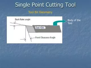
Single-Point Tool Geometry Figure 23.7 ‑ (a) Seven elements of single‑point tool geometry; and (b) the tool signature convention that defines the seven elements ISE 316 - Manufacturing Processes Engineering
Figure 23.9 ‑ Three ways of holding and presenting the cutting edge for a single‑point tool: (a) solid tool, typical of HSS; (b) brazed insert, one way of holding a cemented carbide insert; and (c) mechanically clamped insert, used for cemented carbides, ceramics, and other very hard tool materials ISE 316 - Manufacturing Processes Engineering
Figure 23.10 ‑ Common insert shapes: (a) round, (b) square, (c) rhombus with two 80 point angles, (d) hexagon with three 80 point angles, (e) triangle (equilateral), (f) rhombus with two 55 point angles, (g) rhombus with two 35 point angles. Also shown are typical features of the geometry. ISE 316 - Manufacturing Processes Engineering
Twist Drills • By far the most common cutting tools for hole‑making • Usually made of high speed steel Figure 23.12 ‑ Standard geometry of a twist drill (old:Fig.25.9) ISE 316 - Manufacturing Processes Engineering
Twist Drill Operation • Rotation and feeding of drill bit result in relative motion between cutting edges and workpiece to form the chips • Cutting speed varies along cutting edges as a function of distance from axis of rotation • Relative velocity at drill point is zero, so no cutting takes place • A large thrust force is required to drive the drill forward into hole ISE 316 - Manufacturing Processes Engineering
Twist Drill Operation - Problems • Chip removal • Flutes must provide sufficient clearance to allow chips to be extracted from bottom of hole • Friction makes matters worse • Rubbing between outside diameter of drill bit and newly formed hole • Delivery of cutting fluid to drill point to reduce friction and heat is difficult because chips are flowing in the opposite direction ISE 316 - Manufacturing Processes Engineering
Milling Cutters • Principal types: • Plain milling cutter • Form milling cutter • Face milling cutter • End milling cutter ISE 316 - Manufacturing Processes Engineering
Plain Milling Cutter • Used for peripheral or slab milling Figure 23.13 ‑ Tool geometry elements of an 18‑tooth plain milling cutter ISE 316 - Manufacturing Processes Engineering
Form Milling Cutter Peripheral milling cutter in which cutting edges have special profile to be imparted to work • Important application • Gear‑making, in which the form milling cutter is shaped to cut the slots between adjacent gear teeth, thereby leaving the geometry of the gear teeth ISE 316 - Manufacturing Processes Engineering
Face Milling Cutter • Teeth cut on side and periphery of the cutter Figure 23.14 ‑ Tool geometry elements of a four‑tooth face milling cutter: (a) side view and (b) bottom view ISE 316 - Manufacturing Processes Engineering
End Milling Cutter • Looks like a drill bit but designed for primary cutting with its peripheral teeth • Applications: • Face milling • Profile milling and pocketing • Cutting slots • Engraving • Surface contouring • Die sinking ISE 316 - Manufacturing Processes Engineering
Cutting Fluids Any liquid or gas applied directly to machining operation to improve cutting performance • Two main problems addressed by cutting fluids: • Heat generation at shear zone and friction zone • Friction at the tool‑chip and tool‑work interfaces • Other functions and benefits: • Wash away chips (e.g., grinding and milling) • Reduce temperature of workpart for easier handling • Improve dimensional stability of workpart ISE 316 - Manufacturing Processes Engineering
Cutting Fluid Functions • Cutting fluids can be classified according to function: • Coolants - designed to reduce effects of heat in machining • Lubricants - designed to reduce tool‑chip and tool‑work friction ISE 316 - Manufacturing Processes Engineering
Coolants • Water used as base in coolant‑type cutting fluids • Most effective at high cutting speeds where heat generation and high temperatures are problems • Most effective on tool materials that are most susceptible to temperature failures (e.g., HSS) ISE 316 - Manufacturing Processes Engineering
Lubricants • Usually oil‑based fluids • Most effective at lower cutting speeds • Also reduces temperature in the operation ISE 316 - Manufacturing Processes Engineering
Cutting Fluid Contamination • Tramp oil (machine oil, hydraulic fluid, etc.) • Garbage (cigarette butts, food, etc.) • Small chips • Molds, fungi, and bacteria ISE 316 - Manufacturing Processes Engineering
Dealing with Cutting Fluid Contamination • Replace cutting fluid at regular and frequent intervals • Use filtration system to continuously or periodically clean the fluid • Dry machining ISE 316 - Manufacturing Processes Engineering
Cutting Fluid Filtration Advantages: • Prolong cutting fluid life between changes • Reduce fluid disposal cost • Cleaner fluids reduce health hazards • Lower machine tool maintenance • Longer tool life ISE 316 - Manufacturing Processes Engineering
Dry Machining • No cutting fluid is used • Avoids problems of cutting fluid contamination, disposal, and filtration • Problems with dry machining: • Overheating of the tool • Operating at lower cutting speeds and production rates to prolong tool life • Absence of chip removal benefits of cutting fluids in grinding and milling ISE 316 - Manufacturing Processes Engineering
Tooling • Very hard materials that need other characteristics • Hard – wear resistance • Impact – high impact resistance • Low elasticity