Download
1 / 41
410 likes | 552 Vues
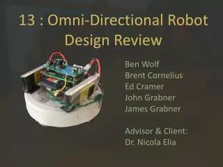
13 : Omni-Directional Robot Design Review. Ben Wolf Brent Cornelius Ed Cramer John Grabner James Grabner Advisor & Client: Dr. Nicola Elia. Problem Statement. The robot designed in 2010 is incomplete Semester One: implement the missing features Semester Two:

E N D
13 : Omni-Directional RobotDesign Review Ben Wolf Brent Cornelius Ed Cramer John Grabner James Grabner Advisor & Client: Dr. Nicola Elia
Problem Statement • The robot designed in 2010 is incomplete • Semester One: • implement the missing features • Semester Two: • Continuation of implementation • Document and test the robot for future team use • Secondary options: • Create multiple robots • Design robots
Current design needs the following: • Analog I/O board • A working IMU • Battery protection and Monitoring • Other features to be worked on • operating system • Documentation • Chassis reorganization
Functional Requirements • I/O board: • Needs to have at least 4 inputs • 12 bit resolution at 1kHz • IMU: • Asses purchased Pololu CHR-6d • Find alternatives if necessary • IMU must be mounted on robot and functioning • Operating System: • Must boot in 30 seconds or less • Must be tolerant of unexpected power loss • Must be compatible with existing hardware
Functional Requirements • Chassis: • Must have outer shell for use with visualization system • Undercarriage wiring must be organized • Use PCBs where possible to simplify manufacture and assembly of robot • Batteryprotection: • Must have automatic disconnect to prevent battery module damage • Battery voltages must be available to OS/AI
Non-Functional Requirements • Maintain function of “legacy” system • Provide documentation for all systems • Characterize robot performance
Risks / Mitigations Risks • Matt Griffith, project maintainer, has moved away • Unclear project definition • Very little documentation • Two robot platforms to support • Preferred robot for future development is non-functional Mitigations • Ask Matt as many questions as possible while he was around • Contact previous team members for additional information • Avoid new features, fix the existing system first • Good documentation practices
Documentation • Documentation for all systems must be created or found • Currently, documentation is unorganized and multiple copies litter computer systems • Should have physical sets of documents • Filing system • Filing cabinet • 3-ring binder with dividers
Documentation • Documentation should include the following • User instructions for robots, visualization system and main server. • Should include FAQ/troubleshooting section • Physical, electrical and software assembly directions for the robot • Datasheet, schematic, and PCB libraries • Correspondences with companies • E-mail logs, invoices, and contact info • Development notes, test procedures and results
Documentation • Must update documentation on current system setup • Currently there is no specific document that says what current setup is. • Go through systems end to end • Set up control server • Calibrate visualization system • Set up ARM development tool chain
I/O Board Research • Re-evaluate the TSADC-16 purchased in 2010 • Manufacturer only supports the board on their hardware • Only operates on 100MHz bus • Development of our own driver would take too long • Alternatives • Purchase new PC/104 board • Use Mesa 4i68 to interface with ADCs • Use RS-232 or parallel port I/O setup
I/O Research • Decided to go with a new PC/104 board based on price and also development time • Considered the following models
I/O Board • After looking over possible choices we went with the WinSystems PCM-MIO-G • Less expensive than other options • We were able to test some of the software and driver before purchase • Has more GPIO pins than other boards • Still has problems with stack configuration
I/O Initial Testing • Driver installed on the robot • Sample programs tested successfully • Accurate to .001 V • Sample rate measurements • A/D conversion process 13-15uS • Transfer data to main memory 75-78uS
I/O Integration • Sample rate is high, reading data is slow • Driver wastes CPU time when used without interrupts • Try to minimize “wait” time and context switches • Group frequently sample channels • Motor driver should be modified to use the interface directly
Operating System Research • Original OS (Ubuntu 10.10) is not appropriate • Existing embedded systems • Familiar Linux (Korebot OS) • Emdebian Linux • RTLinux • Linux from Scratch
Operating System Research • Robot isn't an "embedded" system • Hardware behaves like a desktop PC • Shifted focus towards light weight desktop OS • Some favor towards ease of setup • MicroCore Linux • Emdebian Linux
Operating System Design • Built a kernel for our hardware • Merged the kernel with a Debian installer • The “Development OS” • Installed on a 2.5” hard disk • Used to test TSADC-16 and PCM-MIO-G • Easy to change and modify
Operating System Design • The “Embedded OS” • Delete all unnecessary files • Compress file system into a ramdisk • Install image on compact flash card • Testing • First run with 220MB version during Veisha • OS must be as small as possible to conserve memory
Operating System Testing • Test the effects of various kernel parameters • System timer • Process scheduler • Preemptive thread management • Compiler optimizations • Make sure the OS can handle “hard” shutdowns • OS must boot in 30 seconds or less
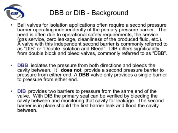
Battery Protection and Monitoring(BPAM) • Current system does not have battery protection • Original plan was to have a system that communicated cell voltages to Eris and warn users when voltage was too low • Decided that active battery protection was needed
BPAM Requirements • Functional Requirements -Cell voltages will be reported to Eris with serial communication -BPAM will cut power to Eris if any cell drops to around 3 Volts -BPAM will be able to work with 2 cell and 3 cell battery packs
BPAM Requirements (cont.) • Non-Functional Requirements -BPAM must have low power consumption. If battery packs are shut off at 10% capacity, the battery pack should last for at least 3 months before cells are ruined
BPAM Research • There are many commercially available battery protection circuits -Not all meet are requirements -Most are designed to protect a fix number of cells -Multi cell devices only had overvoltage protection • Communication will be done with a microcontroller
BPAM Solutions #1 Purchase separate 2 cell and 3 cell protection • Advantages -Tested product -Inexpensive $1~$3 • Disadvantages -Need two different circuits -Not very flexible • Example is the S-8242BBA-I8T1x for 2 cell protection
Selected BPAM –Solution#2 • Microcontroller that is used for monitoring and communication could be used for active battery protection • ADCs available to read cell voltages • Output pins could be used to control shutoff MOSFET • Jumper used to tell microcontroller how many cells the battery pack contains
Solution #2 (cont.) • Advantages -Sensing and communication tasks are combined into one part -Completely adjustable thresholds and fault conditions gives the system more flexibility • Disadvantages -More components -Untested design
IMU Research • IMU • CHR-6d Digital Inertial Measurement Unit previous purchased by last team was destroyed. • Purchased another one to see if it is applicable • Requires testing of output to see if the sampling rate is fast enough to record data that Eris well used for positioning. • Another option is to purchase gyros and accelerometers and build our own system tailored to our own needs.
IMU / Positioning • An IMU is needed to improve accuracy of motion • Additional high speed gyro may be required • Use localization system to estimate robot performance
IMU Testing • Testing lateral accerleration • Use visualization system to record movement of robot • Analyze visual data frame by frame to determine acceleration of robot • Compare to data from IMU • Test Rotational Speed • Use visualization system determine how far and fast robot rotated and compare to data from IMU
Chassis Optimization • Designing a new lid/cover for Eris with camera recognizable design • Addition of power switches • Reorganization of Chassis • Improve wire routing • Use PCBs instead of wires when possible • New wheel design (related project) • Provide test suites and feedback
Adapter Board • Possible solution to hardware stack problem on robot • Will pass through PCI and PC/104 PIN headers • Available space on board to help optimize lower chassis