Download
1 / 20
200 likes | 471 Vues
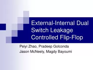
External-Internal Dual Switch Leakage Controlled Flip-Flop. Peiyi Zhao, Pradeep Golconda Jason McNeely, Magdy Bayoumi. Overview. Leakage Problem Control Techniques Flip-Flop Leakage Control Classifications Previous Designs New Design Power-Delay-Leakage Product (PDPL) Results

E N D
External-Internal Dual Switch Leakage Controlled Flip-Flop Peiyi Zhao, Pradeep Golconda Jason McNeely, Magdy Bayoumi
Overview • Leakage Problem • Control Techniques • Flip-Flop Leakage Control Classifications • Previous Designs • New Design • Power-Delay-Leakage Product (PDPL) • Results • Conclusions Center for Advanced Computer Studies UL Lafayette
Leakage Dynamic (CLVdd2 + VddIpeakts)f0->1 VddIleak Power and Leakage in CMOS • Power must be considered to extend battery life of mobile devices and for heat dissipation of integrated circuits • Ptot=Pdyn + Pdp + Pstat Source: J. Rabaey Center for Advanced Computer Studies UL Lafayette
The Problem of Leakage • Technology scaling causes increased leakage power • Leakage currents will cause static power to exceed dynamic power • Ileakage=(W/W0) I010(Vgs-Vt)/S • ITRS 2003 identifies leakage as a “Grand Challenge” • Energy usage in mobile devices is constrained…leakage is a waste of energy Center for Advanced Computer Studies UL Lafayette
Types of Leakage Leakage Diagram Leakage Contributors • I1: PN Junction Reverse Bias Leakage • I2: Subthreshold Leakage • I3/I4: Gate Tunneling and Injection of Hot Carriers • I5: Gate Induced Drain Leakage (GIDL) • I6: Punchthrough K. Roy, Proc. IEEE, 2003 Center for Advanced Computer Studies UL Lafayette
Scaling ITRS 2001 Center for Advanced Computer Studies UL Lafayette
Scaling and Power ITRS 2001 Center for Advanced Computer Studies UL Lafayette
0 0 Transistor Stacking Circuit Level Leakage Control Vds • Transistor Stacking • Vgs < 0 • Vbs < 0 • Vds • Multiple Vt • Dynamic Vt • Supply Voltage Scaling Vgs Vbs K. Roy, Proc. IEEE, 2003 Center for Advanced Computer Studies UL Lafayette
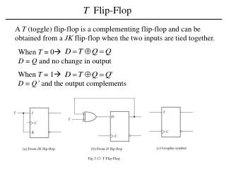
Goal: Flip Flop Leakage Control • Reduce leakage power in flip-flops • Reduce Leakage by: • Utilizing the stack effect • Using high and low Vt transistors • High Vt sleep transistors on main branches Center for Advanced Computer Studies UL Lafayette
VDD function unit external sleep switch single switch internal sleep switch function unit GND Flip-Flop Leakage Control Classifications • Sleep transistors are all high Vt Single External Sleep Switch External-Internal Dual Sleep Switch Center for Advanced Computer Studies UL Lafayette
Previous Design: TGFF • Single sleep transmission gate data retention FF • Sleep disconnects core from ground • Uses virtual ground Mahmoodi-Meimand, ISCAS04 Center for Advanced Computer Studies UL Lafayette
Previous Design: CCFF • Single sleep conditional capture FF • NOR gate controls internal switching activity • No discharge needed if D=1 and Q is already 1 Mahmoodi-Meimand, ISCAS04 Center for Advanced Computer Studies UL Lafayette
high Vt Real VDD low Vt external switch Virtual VDD Sleep P4 P2 P1 Q Q D N1 N2 N3 sleep_bar P3 Clock N6 N7 I I I 1 2 3 N9 sleep_bar Q N5 N4 internal switch function unit New Dual Sleep CDFF • External Sleep: P4 • Internal Sleep: N6, N7 • Conditional Discharge • Implicit Pulsed Center for Advanced Computer Studies UL Lafayette
New Dual Sleep CDFF cont’d • Leakage Reduction: • Use of PMOS instead of NMOS external sleep transistor • Two internal sleep transistors serve dual purpose (sleep mode and clock pulse) • Conditional Discharge • Reduces Switching Activity Center for Advanced Computer Studies UL Lafayette
Power Delay Leakage Product(PDPL) • PDP alone does not take leakage power into enough consideration • Long standby times => leakage becomes significant factor • Average leakage power is sometimes as small as about 0.1% of the dynamic power (depending on FF type) • However, leakage power for certain inputs is as high as 3% or more of the dynamic power • Long standby => higher energy usage not accounted for by PDP only • As leakage power increases in future, PDPL becomes even more valuable FF power from Ramanarayanan, 2002 Center for Advanced Computer Studies UL Lafayette
Results • Simulations completed in 70nm Berkeley Predictive Technology using HSPICE • If only PDP is considered, the Single Sleep CCFF would be the best. • PDPL give the new Dual Sleep CDFF Center for Advanced Computer Studies UL Lafayette
Conclusions • The new Dual-Sleep Conditional Discharge FF has four times less leakage power than the Conditional Capture FF • PDPL is three times smaller for the new flip-flop than that of the CCFF • Use of PMOS external sleep transistor and placement internally of sleep transistors in stack configurations reduces leakage • Use of PDPL instead of PDP is desirable for circuits with long standby times Center for Advanced Computer Studies UL Lafayette
Thank You Center for Advanced Computer Studies UL Lafayette
Author Contacts • Peiyi Zhao: zhao@chapman.edu • Pradeep Golconda: pkg2592@cacs.louisiana.edu • Jason McNeely: jbm8240@cacs.louisiana.edu • Magdy Bayoumi: mab@cacs.louisiana.edu Center for Advanced Computer Studies UL Lafayette
References • K. Roy, S. Mukhopadhyay, H. Mahmoodi-Meimand, “Leakage current mechanisms and leakage reduction techniques in deep-sub micrometer CMOS circuits,” Proc. of the IEEE, vol. 91, no. 2, Feb. 2003 • H. Mahmoodi-Meimand and K. Roy, “Data-retention flip-flops for power-down applications,” Proc. of the 2004 International Symposium on Circuits and Sys-tems, ISCAS04, vol. 2, May 2004, pp. 677-680. • R Ramanarayanan, N Vijaykrishnan, MJ Irwin "Characterizing Dynamic and Leakage Power Behavior in Flip-Flops," ASIC/SOC Conference, 15th Annual IEEE International, 2002 • International Technology Roadmap for Semiconductors, 2003. http://public.itrs.net/ • J. Kao and A. Chandrakasan, “Dual-threshold voltage techniques for low-power digital circuits,” IEEE Jour-nal of Solid State Circuits, vol. 35, no. 7, July 2000, pp. 1009-1018. • F. Hamzaoglu and M.R. Stan, “Circuit-level tech-niques to control gate leakage for sub-100 nm CMOS,” Proc. of the 2002 International Symposium on Low Power Electronics and Design, ISLPED 02, 12-14 Aug. 2002, pp. 60-63. • P. Zhao, T. Darwish and M. Bayoumi, “High-performance and low-power conditional discharge flip-flop,” IEEE Transactions on Very Large Scale In-tegration (VLSI) Systems, vol. 12, no. 5, May 2004, pp. 477-484. • Berkeley Predictive Technology Model (BPTM), http://device.eecs.berkeley.edu/~ptm/download.html • Y. Cao, T. Sato, D. Sylvester, M. Orshansky, and C. Hu, "New paradigm of predictive MOSFET and interconnect modeling for early circuit design," Proc. of IEEE CICC, pp. 201-204, Jun. 2000 • J. Rabaey, A. Chandrakasan, B. Nikolic, “Digital Integrated Circuits: A Design Perspective”. 2nd Ed. 2003, Prentice Hall. Center for Advanced Computer Studies UL Lafayette