Efficient Agricultural Drainage Design Process - Illinois Crop Land
420 likes | 737 Vues
This guide outlines the step-by-step process for designing an effective agricultural drainage system for Illinois crop land. It includes information on drain sizing, outlet design, curve selection, velocity considerations, and layout development.

Efficient Agricultural Drainage Design Process - Illinois Crop Land
E N D
Presentation Transcript
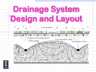
Design Process Flowchart Select DC, Spacing & Depth Background Information (Soils, Topo, Crops) Determine Drain Sizes Installation Drainage Needed Develop System Layout NO Confirm Outlet Determine Grades & Depth NO
Design Process Flowchart Select DC, Spacing & Depth Background Information (Soils, Topo, Crops) Determine Drain Sizes Installation Drainage Needed Develop System Layout NO Confirm Outlet Determine Grades & Depth NO
Design Curves Outlet channels designed according to Curve B will provide excellent agricultural drainage in Illinois. Use this curve for drainage of truck crops, nursery crops, and other specialty crops. Designs based on curve B will provide the best drainage that can normally be justified in agricultural areas.
Design Curves Channels that are designed according to curve C will provide good agricultural drainage in Illinois. This curve is the one most often recommended for drainage of Illinois cropland
Drainage Outlets Designs based on curve D provide satisfactory agricultural drainage as long as frequent overflow does not cause excessive damage. This curve is generally recommended for pasture or woodland. It may also be adequate for drainage of general cropland in northern Illinois, provided that the landowner carries out an excellent maintenance program. Designs based on curve D provide the minimum amount of drainage recommended in Illinois.
Design Curves Drainage CFS/ Acre In/Day Curve 100 Acres (Drainage Coefficient) B 20 4.8 C 8 2.0 D 5 1.2 For comparison: For a 100 acre watershed, RCN = 75, Avg. Slope = 1% in Central Illinois A 2 Yr., 24 Hr. Rainfall yields 1” of Runoff and would result in a Peak Flow of 30 CFS. A 10 Yr., 24 Hr. Rainfall yields 2” of Runoff and would result in a Peak Flow of 70 CFS.
Ditch Configuration Once you know what the capacity of the outlet channel must be, you need to determine the size that will enable it to convey the desired amount of flow without letting the water surface rise above a predetermined elevation. The following sections describe some basic hydraulic concepts that will help you design a channel of the proper size .
Maximum Velocity Soil Texture (ft/sec) Sand or sandy loam 2.5 Silt loam 3.0 Sandy clay loam 3.5 Clay loam 4.0 Clay or silty clay 5.0 Fine gravel, cobbles, or 5.0 graded loam to cobbles Graded mixture silt to cobbles 5.5 Coarse gravel, shales, 6.0 or hardpans Outlet Ditches Velocity The velocity of water flow must be high enough to prevent siltation in the channel but low enough to avoid erosion. Listed on the next page are the maximum velocities for drainage areas of 640 acres or less. The velocity should be no lower than 1.5 feet per second. A lower velocity will cause siltation, which encourages moss and weed growth and reduces the cross section of the channel.
Channel Velocity The most widely used equation for designing outlet channels was developed by Robert Manning in 1890 and is known as Manning's equation: where V = average velocity of flow (ft/sec), n = coefficient of roughness, R = hydraulic radius (ft), s = slope of hydraulic gradient (ft/ft).
Design Process Flowchart Select DC, Spacing & Depth Background Information (Soils, Topo, Crops) Determine Drain Sizes Installation Drainage Needed Develop System Layout NO Confirm Outlet Determine Grades & Depth NO
Design Process Flowchart Select DC, Spacing & Depth Background Information (Soils, Topo, Crops) Determine Drain Sizes Installation Drainage Needed Develop System Layout NO Confirm Outlet Determine Grades & Depth NO
Drain Spacing & Depth • Design for uniform depth throughout system • (depends on layout) • Depth will of course vary on flat and rolling topography
Contour Map
System Layout Cost Differential: $50/acre
Design Process Flowchart Select DC, Spacing & Depth Background Information (Soils, Topo, Crops) Determine Drain Sizes Installation Drainage Needed Develop System Layout NO Confirm Outlet Determine Grades & Depth NO
Result Display
Drainage Coeff.
Design Criteria
Tile Mathematics 10 = 3 x 6 12/2 = 8
Sedimentation Options
Design Chart
Can be Saved