Download
1 / 6
60 likes | 79 Vues
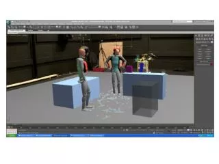
In this 3d Studio Max tutorial, we are going to create a child's tricycle. This is going to give us lots of practice with such things as the Loft modifier, Boolean operations, and much more besides. Before we begin though, it is extremely important to visualise what the end result will look like. You can try drawing a simple sketch, or looking on the net for some good resource images. Just have a set idea in mind before you start. Also, it is important to know the perspective of the finished toy you want. There is no point modeling objects that will never be seen in the final render, unless you are going to animate it as well.<br>

E N D
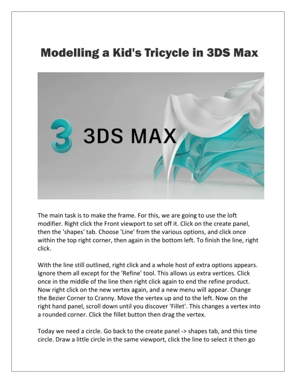
Modelling a Kid's Tricycle in 3DS Max The main task is to make the frame. For this, we are going to use the loft modifier. Right click the Front viewport to set off it. Click on the create panel, then the 'shapes' tab. Choose 'Line' from the various options, and click once within the top right corner, then again in the bottom left. To finish the line, right click. With the line still outlined, right click and a whole host of extra options appears. Ignore them all except for the 'Refine' tool. This allows us extra vertices. Click once in the middle of the line then right click again to end the refine product. Now right click on the new vertex again, and a new menu will appear. Change the Bezier Corner to Cranny. Move the vertex up and to the left. Now on the right hand panel, scroll down until you discover 'Fillet'. This changes a vertex into a rounded corner. Click the fillet button then drag the vertex. Today we need a circle. Go back to the create panel -> shapes tab, and this time circle. Draw a little circle in the same viewport, click the line to select it then go
to create panel -> geometry, and in the drop down menu, choose 'Compound Objects'. A new menu will appear. From this choose 'Loft'. Click the 'Get Shape' switch then click our circle. As you can see, our circle now follows the line like a path. There are a several things we can do to improve the loft though. As the final render will be very close to the camera, we want a sexy smooth frame. So add more vertices to it. To do this we use the 'Skin Parameters' at the bottom of the loft move out. Increasing the Shape Steps value, gives the circle shape more sides making it smoother. Increasing the Path Steps is going to do the same thing to the line. Be careful not to go crazy here, though. The more vertices and polys there are in the scene, that harder it will be on your computer. Don't worry if you aren't happy with the tube, as you can always modify it later. Simply click on the Modify panel. There you will see the loft01 object. If you click on 'shape', you will be able to modify the circle. Additionally, were you to click on 'path', the line would be available for you to change. Now we are going to make a cylinder in the prime viewport. Click the Create panel-> geometry. If you still have the Compound Objects menu, click the drop down list and additionally choose 'Standard Primitives. Choose 'Cylinder'. Notice I have given it 64 sides so it is smooth, and I have reduced the quantity of height segments to as we don't need them. I have also given it 2 cap segments. Later on we use these to make a small hole at the top. Make sure you align it correctly to the tube. Visit: 3dS max courses Select the tube. In the modify tabs, right click 'Loft01' and choose 'Convert to editable Mesh'. Press '1' on the keyboard to enter vertex mode. Now area select the end vertices. Right click and choose rotate. Rotate them 35º as well in addition to move them a little to the left after you scaled them a little. Now for a Boolean operation to join both shapes. Click on the Create panel -> Geometry. Click the drop down menu again and choose 'Compound objects'. Then Boolean. Make sure the operation is set to 'union', click 'Pick Operand B', then the other object. You should now have only one complete object.
Now I want you to use what you have just learnt to make the bar going to the chair. This will just be a cylinder, placed correctly and rotated, and finally a Boolean operation to join them. Now an additional piece of work for you. We are going make the axle for the back wheels using the same methods. First create a sections and use the same circle for the loft: Now for the handlebars. Make a cylinder, rotate it 35º in the entry viewport, and position it correctly. Make sure the radius is less then the frame. To make the positioning better, we are going to make a grid. In the top menu click create-> helpers-> Grid. Drag it in the top viewport, next in the front view, rotate 35º and position just at the top of where the handle bars will appear. With the grid still preferred, go Views-> Grids-> Activate grid objects. At the top of the screen under the main menu items is a box termed the 'Reference Coordinate System'. Click it and from the drop down menu choose 'Grid'. Now our cyndrical tube moves perfectly following the grid object. The handlebars are made in exactly the same way as the frame. You might need to turn heli-copter flight grid object when you are making the line. To do that, just go Views-> Grids-> Activate Home Grid. The handle bars are made in exactly the same way as the frame. You might need to turn off the grid object when you are making the line. For doing that, just go Views-> Grids-> Activate Home Grid. Right click the 'Snaps toggle' at the top of the screen. It is very important to get the 'Midpoint' snap checked. You will see why in just a short minute. Convert the rectangle to an editable Spline and mass media 1 for the vertex mode. Right click for the Refine tool, and with the snaps toggle turned on, click on the outside the house line of the rectangle. You will see a blue line appear and the refined vertex will go exactly in the half process point of the line! Carry on and do as many as there are in the image. Press 2 to enter segment manner and delete the three segments on the left. Then in vertex mode move the two end vertices to your centre.
Still in vertex mode, select every other vertex in the row. You can select multiple vertices by possessing the CTRL key. When you're done, move them a little to the right. Add a couple more vertices to the terminate and drag them to the right Add a couple more vertices to the end and drag them to the right. The Axis isn't in the right place, and this is why our hand grip didn't go all the way over the handlebar. To solve the following, click the Lathe modifier, then Axis. This lets us move the axis to where it should be. Now the Axis is in its correct position. I have also checked the 'Weld Core' box. This just simplifies the nylon uppers. Also, I have increased the number of segments to 32 to give a smoother look. Now we need to copy and turn it to make the other hand grip. A quick and easy way of doing this is by using the Mirror button. Click the idea and you get a new screen appear. The Mirror Axis is how you want the object changed. Here, we want to imitate it along the Y axis. Check 'Copy' to make a clone, and that's it. Just position the new hand grip inside the correct place. The back wheels. Quite easy, these. We will use a simple tube, make the middle vertices bigger, and then find a Mesh Smooth modifier. So first of all, the Create panel -> Geometry -> Tube. Drag it on the Front viewport. Position it correctly and make the width of the wheel quite big. I have reduced the numerous sides to 16 as the Mesh smooth modifier will make it very smooth. Convert it to an Editable Nylon uppers. Press '1' to enter vertex mode, and in the left viewport area select the inner vertices. Notice precisely how bad the tricycle frame looks. I could have changed it before, but as it is going to be hidden by the take, I didn't bother. Change to the Front viewport. Right click and choose 'Scale'. Now drag the vertices so come out of the wheel, repeat, but this time, just choose the middle set of vertices. Now for the Mesh Consistent. Click the Modifier List and click Mesh Smooth from the list. Just one iteration will be enough.
This shape commenced as a circle. I deleted the two segments on the left, and chamfered the middle vertex on the right. Then I increased another vertex between them with the refine tool. This new vertex I chamfered again, and the two vertices I got I moved back. Now add another vertex between the two you just moved back. Delete the two about half and add a Lathe modifier. If you have two or more objects you want to keep together but move around, the best thing to do would be increase them to a group. Go Group-> Group. Type a name you'll remember in the box that appears and mouse click ok. Now select the wheel itself, go Group-> Attach and click the wheel hub. The wheel it on auto-pilot added to the 'Back wheel' group. Very handy! Now use the Mirror button to make a copy. The front wheel is manufactured in exactly the same way as the back two, just make it thinner. Activate our Grid object again, then generate a new Cylinder. Make sure you centre it correctly. Convert it to an editable mesh, then rotate the viewport (not the object! ) so you can see underneath. I have given the cylinder 4 Cap segments. This is why; I want to use the Extrude command to make some of the polys go down each side of the wheel. Press '4' to enter Polygonal mode, after that CTRL select these polys: Now use the Extrude command to create new polys going down each side of the car. With our polys still selected, choose the Scale tool and, making sure the 'grid' reference coordinate system is decided on, scale them down along the X axis. As a final touch, add a Mesh Smooth modifier: The seat. Switch the Grid object to where the seat will begin, then create a box with 4 length and width segments, as well as 3 height segments. Convert it to an editable mesh and add a Mesh smooth modifier. Now it is a question with area selecting vertices and moving them where you need them to
go, turning the mesh smooth on and off as soon as needed to see how it will look.