Chapter 8: Memory Management
Chapter 8: Memory Management. Chapter 8: Memory Management. Background Swapping Contiguous Memory Allocation Paging Structure of the Page Table Segmentation. Objectives. To provide a detailed description of various ways of organizing memory hardware

Chapter 8: Memory Management
E N D
Presentation Transcript
Chapter 8: Memory Management Background Swapping Contiguous Memory Allocation Paging Structure of the Page Table Segmentation
Objectives To provide a detailed description of various ways of organizing memory hardware To discuss various memory-management techniques, including paging and segmentation
Background Program must be brought (from disk) into memory and placed within a process for it to be run Main memory and registers are only storage CPU can access directly Register access in one CPU clock (or less) Main memory can take many cycles Cachesits between main memory and CPU registers
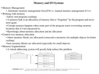
Memory Protection Each process is allocated memory by the OS Protection of memory required to ensure correct operation Process operating in the user mode should be able to access only its memory Should be forbidden from accessing memory of belonging to other processes or kernel memory Base and limit registers Base register indicates the lower bound and limit register the amount of memory Any illegal access will be trapped by the kernel
Base and Limit Registers A pair of baseandlimitregisters define the logical address space.
Binding of Instructions and Data to Memory Instructions and data need to be put into memory before execution Binding is the process of mapping from symbolic to physical addresses Compile time: If memory location known a priori, absolute codecan be generated; must recompile code if starting location changes Load time: Must generate relocatable code if memory location is not known at compile time Execution time: Binding delayed until run time if the process can be moved during its execution from one memory segment to another. Need hardware support for address maps (e.g., base and limitregisters)
Logical vs. Physical Address Space The concept of a logical address space that is bound to a separate physical address spaceis central to proper memory management. Logical address– generated by the CPU; also referred to as virtual address Physical address– address seen by the memory unit (loaded into memory address register) For compile time and load time binding logical and physical addresses are same Logical and physical addresses differ in execution-time address-binding scheme Logical address usually referred to as “virtual address”
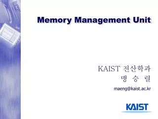
Memory Management Unit Set of all logical addresses generated by program – Logical address space Set of all corresponding physical addresses – physical address space Run-time mapping between logical and physical addresses done by memory-management unit (MMU) Many different MMU schemes Simplest is relocation register – generalization of base register Value in relocation register added to logical address User programs never see physical addresses
Dynamic Loading Requiring entire program and associated data to be in main memory is inefficient and impractical Size of program will be limited by available memory space With dynamic loading a routine is not loaded until it is actually called Routines kept on disk in relocatable format Main program loaded at the beginning Caller routine checks to see if the callee is in main memory If not relocatable linker loader is called to fetch the routine from disk
Dynamic Loading (Contd.) Several advantages Better memory-space utilization Unused routine is never loaded Useful when large amounts of code are needed to handle infrequently occurring cases E.g., exception handling routines No special support from the operating system is required implemented through program design Responsibility of user programs Oses provide library routines
Dynamic Linking Static linking – system libraries are combined by loader to generate binary image Wastes disk-space and main memory because of duplication Dynamic linking -- linking postponed until execution time Stub is included in the image Stub – a small piece of dummy code Knows how to locate the appropriate memory-resident library routine
Dynamic Linking Stub checks if actual routine is in main memory. If not, loads it from disk Replaces itself with the address of the routine, and executes the routine Operating system needed to check if routine is in processes’ memory address Dynamic linking is particularly useful for libraries System also known as shared libraries
Swapping A process can be swapped temporarily out of memory to a backing store, and then brought back into memory for continued execution Backing store– fast disk large enough to accommodate copies of all memory images for all users Must provide direct access to these memory images Swapping in context of round-robin scheduling Roll out, roll in– swapping variant used for priority-based scheduling algorithms Lower-priority process is swapped out so higher-priority process can be loaded and executed
Swapping Swapped-out process can be swapped-in at the same location or at different location Swapping-in at different location possible only in execution-time loading System maintains a ready queueof ready-to-run processes which have memory images on disk Major part of swap time is transfer time Total transfer time is directly proportional to the amount of memory swapped Can be optimized by knowing the amount of memory used by a process Swapping of a process that has pending I/O leads has complications
Contiguous Allocation Main memory usually into two partitions: Resident operating system, usually held in low memory with interrupt vector User processes then held in high memory Relocation registers used to protect user processes from each other, and from changing operating-system code and data Base register contains value of smallest physical address Limit register contains range of logical addresses – each logical address must be less than the limit register MMU maps logical address dynamically
Contiguous Allocation Processes allocated continuous chunk of memory Fixed-size partitions Main memory statically partitioned Each partition holds one process Variable partition On-demand allocation of memory OS keeps track of which parts are available and which parts are occupied Hole – a block (of variable size) that is empty (available)
Contiguous Allocation (Cont.) Multiple-partition allocation Hole – block of available memory; holes of various size are scattered throughout memory When a process arrives, it is allocated memory from a hole large enough to accommodate it Operating system maintains information about:a) allocated partitions b) free partitions (hole) OS OS OS OS process 5 process 5 process 5 process 5 process 9 process 9 process 8 process 10 process 2 process 2 process 2 process 2
Dynamic Storage-Allocation Problem First-fit: Allocate the first hole that is big enough Best-fit: Allocate the smallest hole that is big enough; must search entire list, unless ordered by size Produces the smallest leftover hole Worst-fit: Allocate the largest hole; must also search entire list Produces the largest leftover hole How to allocate memory to an incoming process (of size n) from a list of free holes First-fit and best-fit better than worst-fit in terms of speed and storage utilization
Implementation Issues In theory, variable partition operates at granularity of bytes In practice, keeping track of very small holes is very cumbersome Requires more memory than the size of the hole itself Manage memory at granularity of blocks Memory is broken into fixed sized blocks Processes allocated contiguous blocks of memory depending upon its needs Do not confuse with fixed-size partition
Fragmentation A major drawback of contiguous memory allocation Holes sandwiched between allocated blocks that are not large enough for hosting any process There can be many such holes – total memory in these unusable holes can be more than the needs of several processes External Fragmentation– Entire blocks of memory sandwiched between allocated blocks Internal Fragmentation– Leftover space in a block that is allocated to a process Each process can have at most one partially used block
Fragmentation 50-percent rule – For every N blocks of allocated memory 0.5N blocks lost to fragmentation 33% of available memory lost to fragmentation Reduce external fragmentation by compaction Shuffle memory contents to place all free memory together in one large block Compaction is possible only if relocation is dynamic, and is done at execution time Expensive because it requires massive movement of memory blocks Noncontiguous memory allocation – Paging and Segmentation
Paging Permits physical address space of processes to be noncontiguous Process allocated free blocks irrespective of where they are located (possible in different parts of main memory) Translation from logical to physical addresses gets complicated No longer possible by just adding a relocation value Need to maintain information about all the blocks allocated to a process Divide physical memory into fixed-sized blocks called frames(size is power of 2, between 512 bytes and 8,192 bytes)
Paging (Contd.) Divide logical memory into blocks of same size called pages Logical address space is still contiguous !! Adjacent logical addresses may be mapped to very different physical addresses if they fall in different pages Logical address generated by CPU is divided into: Page number (p)– Indicates the number of the page in which this address falls Page offset (d)– Indicates offset within that page
Address Translation Scheme Suppose size of logical address space is 2m and size of each page is 2n Page number forms higher order (m-n) bits and acts as a index to page table Page offset forms lower order n bits. Combined with base address of the frame to obtain physical address that is sent to memory unit page number page offset p d m - n n
Paging Example 32-byte memory and 4-byte pages
Memory Allocation Process Keep track of all free frames To run a program of size n pages, need to find n free frames and load program Internal fragmentation is still a possibility
Free Frames Before allocation After allocation
Implementation of Page Table Page table is kept in main memory Page-table base register (PTBR)points to the page table Page-table length register (PRLR)indicates size of the page table Every data/instruction access requires two memory accesses – one for the page table and one for the data/instruction Memory access latency becomes high Translation look-aside buffers (TLBs) – Special purpose hardware lookup cache
Effective Access Time Memory translation is a TLB hit if page number found in TLB (i.e., the page-frame lookup can be completed by TLB) TLB miss otherwise TLB hit rate () – fraction (%age) of lookups that are TLB hits Suppose TLB Lookup takes time units and accessing main memory takes up λ time units Effective Access Time(EAT) EAT = (+λ) + (2λ + )(1 – )
TLB & ASIDs Some TLBs have Address-Space Identifiers (ASIDs) that allow them to contain page-frame mappings from multiple processes Each TLB entry associated with ASID that uniquely identifies the associated process When TLB gets a page number for lookup, it checks whether the ASID of the lookup request matches with the ASID of the page number in the TLB If not, the page number belongs to some other process and entry cannot to used for translation and hence treated as TLB miss If TLB does not have ASID, TLB needs to be flushed each time there is a context-switch
Shared Pages Shared code One copy of read-only (reentrant) code shared among processes (i.e., text editors, compilers, window systems). Shared code must appear in same location in the logical address space of all processes. Private code and data Each process keeps a separate copy of the code and data. The pages for the private code and data can appear anywhere in the logical address space.
Structure of the Page Table How is page table organized in main memory? Simpler if entire page table fits in one frame What if does not? Remember memory allocation is non-contiguous Page table itself will be in non-contiguous frames Hierarchical Paging Page table organized in multiple levels Hashed Page Tables Inverted Page Tables
Two-Level Paging Example A logical address (on 32-bit machine with 1K page size) is divided into: a page number consisting of 22 bits a page offset consisting of 10 bits Since the page table is paged, the page number is further divided into: a 12-bit page number a 10-bit page offset Thus, a logical address is as follows:where pi is an index into the outer page table, and p2 is the displacement within the page of the outer page table page number page offset 12 10 10 p2 pi d
Segmentation In paging, there is a disconnect between users view of memory and actual physical memory From a user’s perspective, a program is a collection of distinct parts (e.g., main program, libraries, stack, etc.) Segmentation – A memory-management scheme that supports user view of memory A program is a collection of segments A segment is a logical unit such as: main program procedure, method, object, local variables, global variables, stack, arrays, symbol table etc.
Segmentation (Contd.) Logical address space is a collection of segments Each segment has name and length For implementation, each segment has a unique number Logical addresses specify segment name (number) and offset <segment number, offset>
Logical View of Segmentation 1 4 2 3 1 2 3 4 user space physical memory space
Segmentation Architecture Segment table– maps two-dimensional physical addresses; each table entry has: base– contains the starting physical address where the segments reside in memory limit– specifies the length of the segment Segment-table base register (STBR)points to the segment table’s location in memory Segment-table length register (STLR)indicates number of segments used by a program; segment number s is legal if s < STLR Paging and segmentation both have advantages and disadvantages. Some architectures (Intel Pentium) supports both.